PID Help needed

  • Some of the links on this forum allow SMF, at no cost to you, to earn a small commission when you click through and make a purchase. Let me know if you have any questions about this.
SMF is reader-supported. When you buy through links on our site, we may earn an affiliate commission.

fishwrestler

Smoking Fanatic
Original poster
OTBS Member
Apr 4, 2010
646
34
Loomis,CA
I am turning a cabinet into an electric smoker. I am going to use 220V 20 AMP CIRCUIT. I will use a 3400-watt oven element.
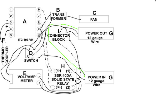
Here is my parts list and a not electrician schematic I did. I would love any productive input or thoughts on this
PID Parts List

  • Inkbird PID Thermostat °F °C Display Stable Digital Temperature Controller Heating Cooling Control ITC106VH 40DA SSR Output Solid State Relay Alarm K Sensor
  • COOLWEST Transformer Driver Power Supply 24W 12V for LED Strip Lights and G4, MR11, MR16 Light Bulbs
  • Anmbest 2PCS 5010 Silent Brushless Cooling Fan 2 pin Brushless 5CM Fans DC 12V 0.1A 50mm X 50mm X 10mm for Cool 3D Printers Parts PC Case CPU Cooler Sleeve Bearing 7 Blades & 50mm Black Fan Finger Grill (2 Pk)
  • Baomain Red Light DPST ON/Off Snap in Boat Rocker Switch 4 Pin 16A/250V UL TUV List (1, Red)
  • DROK Volt Amp Meter, AC 500V 200A Digital Voltmeter Ammeter Panel, 0.39 Inches LED 2in1 Multimeter, 2-Wire Voltage Amperage Tester Gauge with Current Transformer
  • Twidec/2M NPT 1/2"inch (6X100MM) Pipe Thread Temperature Sensor Probe Two Wire Temperature Controller (0~600℃) 304 Stainless Steel K Type Thermocouple MT-205-1/2 & 1 Set GX16 Aviation Plug Socket 2 Pin Screw Type Male Female Metal Aviation Wire Connecto
  • uxcell PG13.5 Cable Gland Waterproof IP68 Nylon Joint Adjustable Locknut with Strain Relief for 7-11.5mm Dia Wire, 2 Pcs
  • 40DA SSR Output Solid State Relay
  • 2 Pack Terminal Block 4 Circuits 20-30A Dual Row Screw Terminals Strip Includes 20 Heat Shrink Wire Connectors Electrical Wiring Kit
  • Beaquicy WB44T10011 Oven Bake Element - Replacement for Ken-more G-E Oven, Replaces: WB44T10059, 820921, AH249286, EA249286, PS249286, B003BIGDEA Voltage ‎220 Volts Wattage ‎3410 watts
 

Attachments

  • MyPID.pdf
    65.6 KB · Views: 45
  • Like
Reactions: flatbroke
I am turning a cabinet into an electric smoker. I am going to use 220V 20 AMP CIRCUIT. I will use a 3400-watt oven element.
Here is my parts list and a not electrician schematic I did. I would love any productive input or thoughts on this
PID Parts List

  • Inkbird PID Thermostat °F °C Display Stable Digital Temperature Controller Heating Cooling Control ITC106VH 40DA SSR Output Solid State Relay Alarm K Sensor
  • COOLWEST Transformer Driver Power Supply 24W 12V for LED Strip Lights and G4, MR11, MR16 Light Bulbs
  • Anmbest 2PCS 5010 Silent Brushless Cooling Fan 2 pin Brushless 5CM Fans DC 12V 0.1A 50mm X 50mm X 10mm for Cool 3D Printers Parts PC Case CPU Cooler Sleeve Bearing 7 Blades & 50mm Black Fan Finger Grill (2 Pk)
  • Baomain Red Light DPST ON/Off Snap in Boat Rocker Switch 4 Pin 16A/250V UL TUV List (1, Red)
  • DROK Volt Amp Meter, AC 500V 200A Digital Voltmeter Ammeter Panel, 0.39 Inches LED 2in1 Multimeter, 2-Wire Voltage Amperage Tester Gauge with Current Transformer
  • Twidec/2M NPT 1/2"inch (6X100MM) Pipe Thread Temperature Sensor Probe Two Wire Temperature Controller (0~600℃) 304 Stainless Steel K Type Thermocouple MT-205-1/2 & 1 Set GX16 Aviation Plug Socket 2 Pin Screw Type Male Female Metal Aviation Wire Connecto
  • uxcell PG13.5 Cable Gland Waterproof IP68 Nylon Joint Adjustable Locknut with Strain Relief for 7-11.5mm Dia Wire, 2 Pcs
  • 40DA SSR Output Solid State Relay
  • 2 Pack Terminal Block 4 Circuits 20-30A Dual Row Screw Terminals Strip Includes 20 Heat Shrink Wire Connectors Electrical Wiring Kit
  • Beaquicy WB44T10011 Oven Bake Element - Replacement for Ken-more G-E Oven, Replaces: WB44T10059, 820921, AH249286, EA249286, PS249286, B003BIGDEA Voltage ‎220 Volts Wattage ‎3410 watts
I’m in for the ride.
 
  • Like
Reactions: smokin peachey
oops I posted the wrong schematic
 

Attachments

  • PID.jpg
    PID.jpg
    629.7 KB · Views: 86
OK i have changed one thing with some input from an electrician friend. I am going to run 10 gauge wire in and out of the box and go with 30 AMP Breaker and 30 amp 220v switch
 
thank you I also sent JC in GC a message

Responded to your message. Glad to help you get this wired up properly. I am not familiar with that controller. I will have to look up the pinout. Also, it would help if I had the parts list of the other parts.

Thanks,

JC :emoji_cat:
 
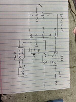
Here is what I came up with. Does this help?

JC
 

Attachments

  • IMG_0505.jpeg
    IMG_0505.jpeg
    131.2 KB · Views: 73
Responded to your message. Glad to help you get this wired up properly. I am not familiar with that controller. I will have to look up the pinout. Also, it would help if I had the parts list of the other parts.

Thanks,

JC :emoji_cat:
Thank you I responded to your message and sent my complete parts list and how i think the wiring should go
 
This is for a 220v 30 amp circuit? This looks like the 110V schematics I see. Will they work the same? Do you recommend removing the volt/amp meter ?
It will work fine at 220v 30 amps. Not sure why you need the meter but it is always nice having more info.
 
Looking at these diagrams I am confused... JC.. You have wht and Blk going to the SSR... Are not the control wires (Pos 8, Neg 6) low voltage (12v) ? For 220v I have mine wired with Wht going straight to the element and Blk going through SSR (for contro) and then to the element.. You are feeding both L1 (wht) and L2 (blk) to the SSR ? Yea... I am confused ...
 
Looking at these diagrams I am confused... JC.. You have wht and Blk going to the SSR... Are not the control wires (Pos 8, Neg 6) low voltage (12v) ? For 220v I have mine wired with Wht going straight to the element and Blk going through SSR (for contro) and then to the element.. You are feeding both L1 (wht) and L2 (blk) to the SSR ? Yea... I am confused ...
Ok it's not just me JA]ckDanls did you see my (terrible) Schematic
 
  • Haha
Reactions: JC in GB
Looking at these diagrams I am confused... JC.. You have wht and Blk going to the SSR... Are not the control wires (Pos 8, Neg 6) low voltage (12v) ? For 220v I have mine wired with Wht going straight to the element and Blk going through SSR (for contro) and then to the element.. You are feeding both L1 (wht) and L2 (blk) to the SSR ? Yea... I am confused ...
You are correct. Black goes to the heater then to the SSR. White goes to the low side of the SSR. That is what my drawing shows.

JC
 
OK i have changed one thing with some input from an electrician friend. I am going to run 10 gauge wire in and out of the box and go with 30 AMP Breaker and 30 amp 220v switch
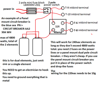
I'm going to chime in here. I did a drawing for a guy a while ago for 220vac PID connection. Make sure you ground eveything metal. If you use terminal, use ring termanls on the grounds. One more thing. If that PID controller will accept PT-100 sensors you should use one. Auber Instruments has some nice ones that aren't expensive.
 

Attachments

  • Dual element PID-3png.png
    Dual element PID-3png.png
    51 KB · Views: 52
SmokingMeatForums.com is reader supported and as an Amazon Associate, we may earn commissions from qualifying purchases.

Latest posts

Hot Threads

Clicky