Want to know how to setup the HeaterMeter PID Controller with Wifi to work with the MES? Here you go :)
[h1]Table of Contents[/h1]
When it comes to controlling an electric smoker such as the Masterbuilt Electric Smoker (MES) many have opted to rewire it and use a 3rd party controller they buy or build such as a PID controller (Proportional, Integral, Derivative).
The HeaterMeter is a Raspberry Pi device (small computer device) that was initially built to control Charcoal Smokers using PID controller logic to work with a blower fan to stoke the coals of a smoker. The HeaterMeter device provides great features for controlling and monitoring a cook/smoke such as:
There is not much information available out there online for using the HeaterMeter to work with an electric smoker so I figured I would post some details for anyone who wants to go this route.
The formal HeaterMeter documentation can be found here: https://github.com/CapnBry/HeaterMeter/wiki
IMPORTANT: Remember the HeaterMeter was not designed for electric smokers so the PID tuning information will not work exactly as documented.
[h2]2. HeaterMeter Mod Design[/h2]
The following are the HeaterMeter (HM) Mod Designs and such that are needed to put the HM to use with an Electric Smoker (MES).
[h3]MES Rewire[/h3]
First off the electric smoker must be rewired to work with the HM controller or any 3rd party controller. This section will not go into detail on rewiring an MES but I may do a separate post and link to it from here. There is quite a bit of good info on this forum for rewiring an MES so feel free to Google away on it.
In short, the MES must be rewired so that the Power chord is wired to bypass the MES controller and circuit board to run electricity to the MES heating element.
Also, It is wise to include the existing MES Rollout Limit Saftey Switch into the rewire job so should the MES reach a high enough temperature to trigger the rollout limit switch, the switch will cut off power to the heating element in order to keep the MES from burning down and causing any dangerous fire situations.
[h3] [/h3][h3]HeaterMeter Based Controller Box Wiring and Diagrams[/h3]
(FEEDBACK ENCOURAGED: I am not an electrician so if there is any content in here that is misstated, poorly described, or potentially dangerous please feel free to let me know and I will fix or remove the content so it is not out there to confuse or cause a dangerous situation.)
DISCLAIMER: This information is a guideline and you should consult an electrical professional concerning the information below and for your electrical wiring/setup project.
Once the MES is rewired for a 3rd party controller the next order of business is to create a Controller Box to hold the wiring and electrical components needed to control the MES smoker.
How is the HeaterMeter (HM) or any 3rd party controller used to control a smoker?
Well in short the HM will measure the temperature in the smoker with a probe and based on the Set Temperature, the HM will send a control signal to switch power on/off to a device that will work to increase the smoker temperature or to stop.
The original HM intent was to send an outpout signal to turn on/off a blower fan to stoke coals at 0-100% of the fan's blowing capability. No need to go full blast with the fan all the time.
Using the HM with an MES or any Electrical Smoker is almost the same except there are some differences that matter.
What happens when a HM is used with an MES is that the HM will still send the signal but it should instead go to a switch called an SSR (Solid State Relay) not a blower fan.
The SSR is wired to have the 110V electrical power current coming in and wired to send the 110V electrical current out.
When the SSR receives the signal from the HM, the SSR will switch on to allow the power to flow through itself and onward to the MES chord which is rewired to go to the MES heating element.
The MES heating element will heat until the Set Temp is detected by a probe at which point the HM will stop sending signal to the SSR thereby switching the SSR to the Off position so no more power goes to the MES heating element.
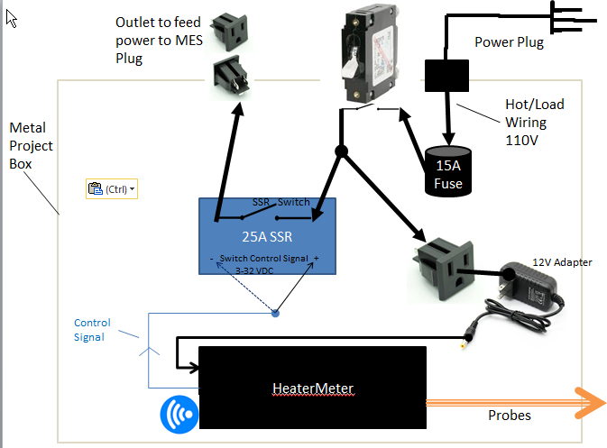
Here is a Diagram to help picture it:
Now with that you understand how the HeaterMeter will control a rewired MES we can proceed to more realistic diagrams and concepts.
Things to Consider:
Hot/Load Wiring Design and Diagram
The hot/load wiring will need to:
Neutral Wiring Design and Diagram
The Neutral wiring to complete the electrical circuit will need to:
Ground Wiring Design and Diagram
Finally the ground wiring will need to be setup so that if there is an issue the electrical current can go to ground for safety sake. IMPORTANT: Read up on grounding devices for full understanding of how and why you should do it :
Safety
Anytime you mess with electricity be sure to take the proper precautions such as:
It is best to test and setup the HeaterMeter (HM) device before going through the effort of building and wiring up a controller box.
It is best to know that various components of a build/project work before assembling everything and discovering an issue but not knowing where it exists.
The HM has multiple areas to be setup but in short you will need to ensure it powers on properly, setup wifi capabilities, make life easier by setting up a Static IP for the HM, and finally perform PID tunings and configurations needed to work best with an Electric Smoker.
[h3]Common Setup[/h3]
Perform the following steps for performing the initial necessary setup:
What in the world is a "Static IP Setup"?
Well you will notice that as you unplug or turn off your HeaterMeater (HM) and then turn it back on and hit the http://heatermeter.com/devices/ page that the Address value may/will change. A changing IP is not desirable.
The IP Address is the location on your network that a device is assigned so it can be located. Much like your home address is the location assigned to your home so it can be physically located in the world. Your home router will assign the IP to the HM device however it sees fit and will not always use the same IP address.
Configuring a static IP is not mandatory but it makes life easy so you don't need to look up the new address every time to hit the dashboard and more importantly when you use an app like PitDroid on your phone to monitor and control things form your phone you will not need to enter the new IP address in every time for the app to connect to the HM and work properly.
Now everyone is likely to have a different brand and model of router so I will post some instructions for a Netgear router on how to do this. These instructions are basically the same for any/all routers so they will give you the idea of what you need to do for yours.
The information for configuring the HeaterMeter (HM) to use with an electric smoker is not easy to come by and has to be pieced together from all kinds of online sources. Well I believe this section will act as a consolidated list of the settings needed for the HM to work well with an electric smoker like the MES.
Non-PID Settings (these are mandatory):
PID Settings:
Every kind of PID controller could potentially have a different set of steps/logic (algorithm) it uses to manage control behavior. The HM PID steps and settings result in a slightly different behavior than the Auber electronic PID controller I have used as well. The documentation for the HM PID behavior therefore does not exactly apply to an electric smoker like it does for a blower fan and working with coals in a more traditional smoker.
I will explain how these settings and the HM will work.
In all what will happen with the following PID settings is that the "I" will bring your temp up to the set temp and along with the "P" will overshoot by about 7-13 degrees.
At that point the "D" will act like a parachute allowing the temp to slowly drop to the set temp. The "D" is in a loosing battle but keeps the temp from plummeting.
Once the temp drops below the set temp the "I" will begin to kick in to bring the temp back up to the set temp:
At this point the "D" may kick in to cut the power at time to keep the temp from increasing too rapidly. Then the "D" will work again to slowly drop the temp back down to the set temp where then the "I" will kick in to bring the temp back up to the set temp.
This whole time the "P" is doing minimal work other then being the number that "I" and "D" will help perform it's calculations to control the heat.
Ok with all of that explained away, let's get to the PID settings, here they are:
So for best performance follow the PID tunings and use the lower rack first and then move upwards to higher racks.
The bottom 2 racks are the most consistently close to the set temp.
The top 2 racks have a greater temp discrepancy and may have trouble hitting the set temp.
I have noticed though that each rack in my system holds within it's temp range though the temp range may not be as close to the set temp as the bottom rack or the bottom 2 racks.
So in short, if your top rack is 15 degrees lower than the set temp and swings by 5 degrees then you can pretty much expect it to be consistent with that behavior.
This is why I use the bottom 2 racks as much as possible to get as close to the set temp with the lowest temp swing as possible.
I wish I could say that the MES could have an even temp all over with the HM setup but I just don't think it is possible with the initial design. I've tried a bunch of stuff and the best I can get is predictable results, minimal temp swings, and greater control than the stock MES controller behavior. I can now do sausage, bacon, chicken with edible skin, you name it I can do it with confidence!
[h2]5. Mods that exist in my system that may give me different/better results than another setup[/h2]
I have done quite a bit of mod'ing to ensure I get minimal temp swings, can actually hit my set temp, and to be able to manage smoke separately from heat management/cooking.
Here is a list of materials that I used for the HM and Controller box mods. More materials may need to be purchased but here is the best I could do along with prices. I would love to post links but I think that is frowned upon unless someone states otherwise for this post.
I need to seal up the extra space around the new switch that does not melt below.
[h1]Table of Contents[/h1]
Overview- HeaterMeter Mod Design
- MES Rewired - just mention don't go into detail
- HeaterMeter Based Controller Box Wiring and Diagrams
- HeaterMeter Setup
- Common Setup
- STATIC IP SETUP
- ADDITIONAL ELECTRIC SMOKER SETUP
- ELECTRIC SMOKER PID Tuning Settings
- MES Cooking/Smoking Setup for Best Results
- Mods that exist in my system that may give me different/better results than another setup
- Materials list
- Pics of My HeaterMeter Controller Mod :)
When it comes to controlling an electric smoker such as the Masterbuilt Electric Smoker (MES) many have opted to rewire it and use a 3rd party controller they buy or build such as a PID controller (Proportional, Integral, Derivative).
The HeaterMeter is a Raspberry Pi device (small computer device) that was initially built to control Charcoal Smokers using PID controller logic to work with a blower fan to stoke the coals of a smoker. The HeaterMeter device provides great features for controlling and monitoring a cook/smoke such as:
- Wifi control setting and monitoring capability
- Graphical Monitoring of a cook/smoke with times, probe temps, and the history of the entire cook/smoke
- Web page based interfaces to change control settings such as smoker set temp, probe offsets, graphing options, etc.
- Additional interfaces so Apps like PitDroid can be written to monitor and control the smoke from a mobile device App or a software application you can write on your own if you have that skillset and background
- Phone app support to control and monitor your smoker from your phone
- Multiple probes that can be managed and monitored, 3-4 probes depending on device built
- PID control, which allows for tuning according to your smoker behavior and environment to get the steadiest and best performance
There is not much information available out there online for using the HeaterMeter to work with an electric smoker so I figured I would post some details for anyone who wants to go this route.
The formal HeaterMeter documentation can be found here: https://github.com/CapnBry/HeaterMeter/wiki
IMPORTANT: Remember the HeaterMeter was not designed for electric smokers so the PID tuning information will not work exactly as documented.
[h2]2. HeaterMeter Mod Design[/h2]
The following are the HeaterMeter (HM) Mod Designs and such that are needed to put the HM to use with an Electric Smoker (MES).
[h3]MES Rewire[/h3]
First off the electric smoker must be rewired to work with the HM controller or any 3rd party controller. This section will not go into detail on rewiring an MES but I may do a separate post and link to it from here. There is quite a bit of good info on this forum for rewiring an MES so feel free to Google away on it.
In short, the MES must be rewired so that the Power chord is wired to bypass the MES controller and circuit board to run electricity to the MES heating element.
Also, It is wise to include the existing MES Rollout Limit Saftey Switch into the rewire job so should the MES reach a high enough temperature to trigger the rollout limit switch, the switch will cut off power to the heating element in order to keep the MES from burning down and causing any dangerous fire situations.
[h3] [/h3][h3]HeaterMeter Based Controller Box Wiring and Diagrams[/h3]
(FEEDBACK ENCOURAGED: I am not an electrician so if there is any content in here that is misstated, poorly described, or potentially dangerous please feel free to let me know and I will fix or remove the content so it is not out there to confuse or cause a dangerous situation.)
DISCLAIMER: This information is a guideline and you should consult an electrical professional concerning the information below and for your electrical wiring/setup project.
Once the MES is rewired for a 3rd party controller the next order of business is to create a Controller Box to hold the wiring and electrical components needed to control the MES smoker.
How is the HeaterMeter (HM) or any 3rd party controller used to control a smoker?
Well in short the HM will measure the temperature in the smoker with a probe and based on the Set Temperature, the HM will send a control signal to switch power on/off to a device that will work to increase the smoker temperature or to stop.
The original HM intent was to send an outpout signal to turn on/off a blower fan to stoke coals at 0-100% of the fan's blowing capability. No need to go full blast with the fan all the time.
Using the HM with an MES or any Electrical Smoker is almost the same except there are some differences that matter.
What happens when a HM is used with an MES is that the HM will still send the signal but it should instead go to a switch called an SSR (Solid State Relay) not a blower fan.
The SSR is wired to have the 110V electrical power current coming in and wired to send the 110V electrical current out.
When the SSR receives the signal from the HM, the SSR will switch on to allow the power to flow through itself and onward to the MES chord which is rewired to go to the MES heating element.
The MES heating element will heat until the Set Temp is detected by a probe at which point the HM will stop sending signal to the SSR thereby switching the SSR to the Off position so no more power goes to the MES heating element.
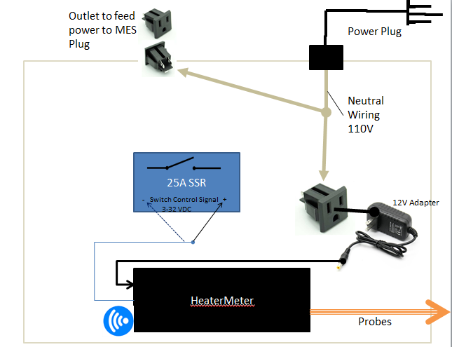
Here is a Diagram to help picture it:

Now with that you understand how the HeaterMeter will control a rewired MES we can proceed to more realistic diagrams and concepts.
Things to Consider:
- It would not be safe to just have wires running all over feeding 110V of power to devices like an SSR that are exposed so a controller box would need to be built to house and protect everything.
- The controller box would need a power plug to plug into a wall outlet to get 110V power to control the MES.
- The controller box would need an outlet so the MES could plug into the controller box to receive 110V of power from the SSR to power off/on the heating element
- It would be necessary to run a fuse in to the system so that if any power surges or electrical issues cause a pull of more power than desired the current could be cut off for safety reasons by the fuse blowing
- It would also be nice to have an On/Off switch to the whole controller bus to control the power from the wall into the controller box rather than on/off being dictated by plugging/unplugging to the wall
- The HM doesn't take 110V it takes 12V so the voltage would need to be stepped down to power the HM. This is done through a 12V adapter plug but it is nice to hide that plug in the controller box, not to mention wiring up an easy way to plug a 12V power plug to the incoming 110V power
Hot/Load Wiring Design and Diagram
The hot/load wiring will need to:
- Come from the 110V power outlet into the Controller Box
- 110V should first go to a 15A fuse
- From the 15A fuse to an On/Off Switch that can handle 20A or more of continusous current.
I suggest you buy something metal and not Chinese. I burned up two 20A Rocker switches that were cheap chinese junk. I then went overboard and bought a 100A Marine Boat Breaker Toggle Switch and have had no issues with that hardcore switch :) - From the On/Off Switch wire out to a split point. You will split to the:
- SSR
- From the SSR to an Outlet installed in/on the controller box. This what the MES will plug into to receive power.
- Outlet or Female end of a power/extension cord for the HM 12V adapter power plug to plug into
- This will connect to the 12V adapter power supply
- The 12V adapter power supply to the HeaterMeter, to power the HM
- SSR
Neutral Wiring Design and Diagram
The Neutral wiring to complete the electrical circuit will need to:
- Come from the 110V power outlet into the Controller Box
- Then to a Split Point. You will split to :
- To the same Outlet installed in/on the controller box that the SSR Hot/Load is wired to. This what the MES will plug into to receive power and will need both the Hot/Load and Neutral wired to it.
- The Same Outlet or Female end of a power/extension cord for the HM 12V adapter power plug to plug into
- The HM 12V adapter power plug needs both Hot/Load and Neutral wired to it
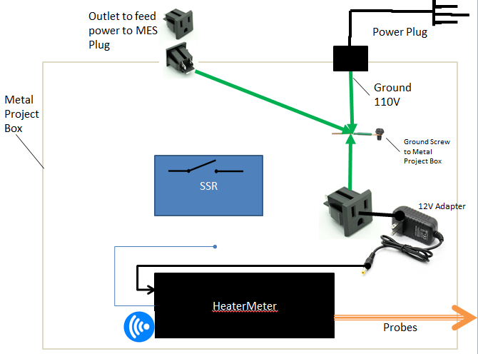
Ground Wiring Design and Diagram
Finally the ground wiring will need to be setup so that if there is an issue the electrical current can go to ground for safety sake. IMPORTANT: Read up on grounding devices for full understanding of how and why you should do it :
- From the 110V power outlet into the Controller Box
- To ground screw fastened to metal Controller Box
- From the same Outlet installed in/on the controller box that the SSR Hot/Load is wired to
- To ground screw fastened to metal Controller Box
- From the Same Outlet or Female end of a power/extension cord for the HM 12V adapter power plug to plug into
- To ground screw fastened to metal Controller Box
Safety
Anytime you mess with electricity be sure to take the proper precautions such as:
- Using the proper tools to test with like a MultiMeter
- Use protective gear to prevent electrical shock or worse
- Make sure the device is properly grounded
- Do not touch wires or components with hands while the device is plugged in
- Be sure to insulate any bare connectors, wires, or exposed metal that will have current running through it
- Consult an electric professional for assistance
It is best to test and setup the HeaterMeter (HM) device before going through the effort of building and wiring up a controller box.
It is best to know that various components of a build/project work before assembling everything and discovering an issue but not knowing where it exists.
The HM has multiple areas to be setup but in short you will need to ensure it powers on properly, setup wifi capabilities, make life easier by setting up a Static IP for the HM, and finally perform PID tunings and configurations needed to work best with an Electric Smoker.
[h3]Common Setup[/h3]
Perform the following steps for performing the initial necessary setup:
- Formal HM documentation can be found at the following link but you will need to sort through it to find the documentation that is relevant to this/your build. My information below is kind of the cliff notes versions of the documentation here: https://github.com/CapnBry/HeaterMeter/wiki/HeaterMeter-4.x-Software
- Plug probes into HM
- IMPORTANT: Maverick probes do NOT need to plug in all the way, they will plug in about 3/4 of the way.
If you plug in all the way they will not register, you will need to pull them out to the next "stop". I think the formal HM documentation says you may chance breaking the port on the HM, but I have pushed all the way into the ports a number of times and had not broke anything but I try to avoid it.
- IMPORTANT: Maverick probes do NOT need to plug in all the way, they will plug in about 3/4 of the way.
- Plug Ethernet chord into HM and into your router
- Plug USB WIFI adapter into HM
- Plug 12V Power Adapter chord into HM and then put the 12V plug into the wall power socket. The HM device will boot up automatically, give it about 30 -45 seconds to fully boot up. You should see some output displayed on the HM device LCD screen.
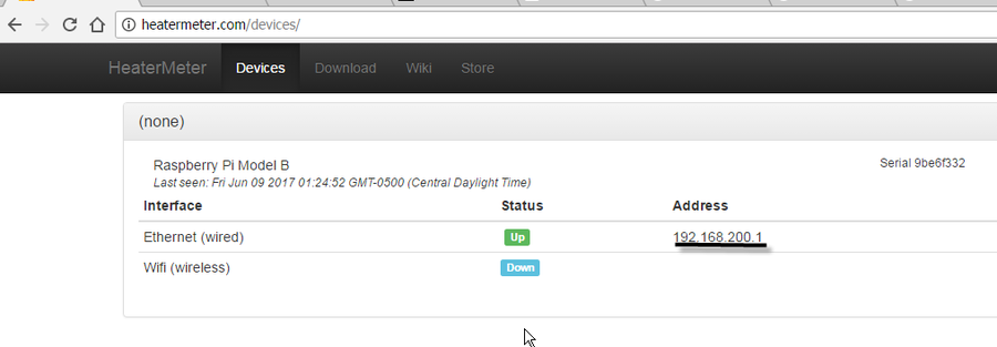
- Once the HM boots up get on a computer that is connected to your network and go to http://heatermeter.com/devices/ and you should see your device registered
- Click the Address IP link (underlined in the image below) and it will open the Dashboard where you can log in and set up other configurations
- Click the Address IP link (underlined in the image below) and it will open the Dashboard where you can log in and set up other configurations
- IMPORTANT (taken from formal documentation): Note: If your wifi SSID or password contains quotes (single ' or double ") then you're going to experience a nightmare trying to get this to work. E.g. your SSID is "Bryan's Wifi" = bad.
- Follow Wifi Setup Steps here at the section with the header "Wireless Client Setup via Web Config step-by-step" https://github.com/CapnBry/HeaterMe...less-client-setup-via-web-config-step-by-step
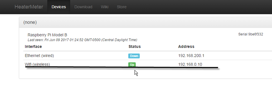
- After following the Wifi Setup Setps, Unplug the ethernet cable from the HM and reboot now that Wifi client has been configured, you cannot have both plugged in once configured.
If your device does not register at http://heatermeter.com/devices/ or cannot access via the Wifi address after reboot that is because you have the issue where both the ethernet and wifi network cannot be setup on the same subnet (router stuff) follow the next step if you have this issue (I had the issue as well so don't be afraid)- IMPORTANT: I had to follow the troubleshooting information here at the header "My Wifi interface never gets an IP address": https://github.com/CapnBry/HeaterMe...ng#my-wifi-interface-never-gets-an-ip-address
(TODO: need to post some pics for this important instruction)
- IMPORTANT: I had to follow the troubleshooting information here at the header "My Wifi interface never gets an IP address": https://github.com/CapnBry/HeaterMe...ng#my-wifi-interface-never-gets-an-ip-address
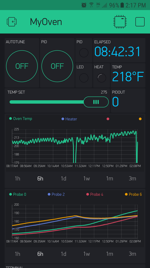
- Once Wifi is properly setup you should see the following and be able to click the Address IP link for the wifi line and get to the HM dasbhoard
Dashboard Example Here:
- d
What in the world is a "Static IP Setup"?
Well you will notice that as you unplug or turn off your HeaterMeater (HM) and then turn it back on and hit the http://heatermeter.com/devices/ page that the Address value may/will change. A changing IP is not desirable.
The IP Address is the location on your network that a device is assigned so it can be located. Much like your home address is the location assigned to your home so it can be physically located in the world. Your home router will assign the IP to the HM device however it sees fit and will not always use the same IP address.
Configuring a static IP is not mandatory but it makes life easy so you don't need to look up the new address every time to hit the dashboard and more importantly when you use an app like PitDroid on your phone to monitor and control things form your phone you will not need to enter the new IP address in every time for the app to connect to the HM and work properly.
Now everyone is likely to have a different brand and model of router so I will post some instructions for a Netgear router on how to do this. These instructions are basically the same for any/all routers so they will give you the idea of what you need to do for yours.
- Google the Static IP Setup instructiosn for your router
- Open a web browser on a computer that is on your network (IE, Firefox, Chrome, etc. are all web browsers)
- In the web browser address bar enter the address to your router configuration page often it is http://192.168.0.1
- Login, IMPORTANT: it is a good idea to change the default router login password (THIS IS NOT THE SAME AS YOUR WIFI PASSWORD so don't confuse the two) to something strong and unique. If you keep/use the default router login password someone can easily Google what the password is for the model of your router and that is bad
- Follow the next steps for a Netgear Static IP Setup documented here https://kb.netgear.com/25722/How-do-I-reserve-an-IP-address-on-my-NETGEAR-router:
- Launch a web browser from a computer or mobile device that is connected to your router’s network.
- Enter http://www.routerlogin.net.
A login window displays. - Enter the router user name and password.
The user name is admin. The default password is password. The user name and password are case-sensitive.
The BASIC Home page displays. - Select ADVANCED > Setup > LAN Setup.
The LAN page displays. - In the Address Reservation section, click the Add button.
The page adjusts. - In the IP Address field, type the IP address to assign to the computer or server.
Choose an IP address from the router’s LAN subnet, such as 192.168.1.x. (192.168.0.110 would be a good choice for the HeaterMeter) - Type the MAC address of the computer or server.
IMPORTANT: Get your HeaterMeter MAC address like this while it is connected and running - If the HM is already on your network, you can copy its MAC address from the Attached Devices page and paste it here. - Click the Apply button.
The reserved address is entered into the table.
The reserved address is not assigned until the next time the HeaterMeter contracts the router’s DHCP server. Reboot the HM and check that it now is bound to the IP you assigned by checking the page http://heatermeter.com/devices/
The information for configuring the HeaterMeter (HM) to use with an electric smoker is not easy to come by and has to be pieced together from all kinds of online sources. Well I believe this section will act as a consolidated list of the settings needed for the HM to work well with an electric smoker like the MES.
Non-PID Settings (these are mandatory):
- //TODO: Add section on deleting the BSSID value to avoid issues should you change router for a new one or due to old router dying!!!!
- Fan Output: Pulse
- min: 100%
- max: 100%
- startup max: 100%
- Lid Open Detection (this setting makes NO sense for an electrical smoker and will cut the heat off, it drove me nuts before I figured out how to basically disable it)
- Activate at: 0%
- Continue for: 30 seconds

PID Settings:
Every kind of PID controller could potentially have a different set of steps/logic (algorithm) it uses to manage control behavior. The HM PID steps and settings result in a slightly different behavior than the Auber electronic PID controller I have used as well. The documentation for the HM PID behavior therefore does not exactly apply to an electric smoker like it does for a blower fan and working with coals in a more traditional smoker.
I will explain how these settings and the HM will work.
- Proportional "P": This is the setting that will be used for building temp in most PID controllers and more importantly is used to calculate how the "I" and "D" settings will respond help control the system. Believe it or not the "P" tuning is really not going to do the heavy lifting here but is needed for the "I" and "D" settings to do the major work in this configuration
- Integral "I": This is the setting traditionally helps bring the P value into tune helping to avoid major dips or major overshoots of temperature. Well with these HM PID tuning values and an electric smoker the "I" tuning seems to only work on bringing the temperature up to the set point when the temperature is below the set point. That's the behavior you will see with the "I". So the "I" tuning is mostly responsible for getting up to the set temp. The value should be low because every second the temp is under the set temp the "I" value makes the heat output signal grow and last longer. You do not want this to grow too much for too long.
- Derivative "D": This is the trickiest setting to deal with and is the MOST important in use with the HM and the electric smoker. The "D" looks back in time to figure out the rate of change that is occurring. If the temp change is growing too fast it will cut the outpout so the temp stops growing. Alternatively, if the temp is dropping too fast the setting will increase output so that the heating element cuts on and keeps the temp from dropping too fast. The "D" will be the major player along with the "I" setting for the PID control of the electric smoker with the use of the HM.
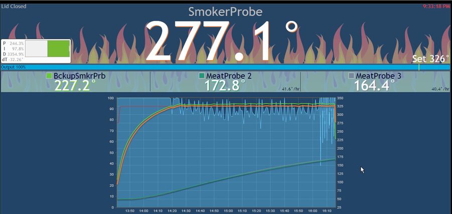
In all what will happen with the following PID settings is that the "I" will bring your temp up to the set temp and along with the "P" will overshoot by about 7-13 degrees.
At that point the "D" will act like a parachute allowing the temp to slowly drop to the set temp. The "D" is in a loosing battle but keeps the temp from plummeting.
Once the temp drops below the set temp the "I" will begin to kick in to bring the temp back up to the set temp:
At this point the "D" may kick in to cut the power at time to keep the temp from increasing too rapidly. Then the "D" will work again to slowly drop the temp back down to the set temp where then the "I" will kick in to bring the temp back up to the set temp.
This whole time the "P" is doing minimal work other then being the number that "I" and "D" will help perform it's calculations to control the heat.
Ok with all of that explained away, let's get to the PID settings, here they are:
- P: 5
- I: 1
- D: 104
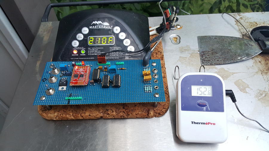
- Probe and Rack Placement: Use the lowest rack position of the MES/electric smoker. Place the smoker probe at the bottom of the rack in the center . I use an alligator clip Thermocouple probe so it clips directly underside the rack at the bottom grate level.
- Temp Expectations: Expect within a -+2 swing in temp around your set temp. Temp range I have tested is 100F through to 325F. At temps over 175F or so the temp swing gets even smaller! Once thing I do at higher temps is set 1 degree high, so for a temp of 225F I set to 226F and the temp mostly sits between 225.5F to 226.3F.
So for best performance follow the PID tunings and use the lower rack first and then move upwards to higher racks.
The bottom 2 racks are the most consistently close to the set temp.
The top 2 racks have a greater temp discrepancy and may have trouble hitting the set temp.
I have noticed though that each rack in my system holds within it's temp range though the temp range may not be as close to the set temp as the bottom rack or the bottom 2 racks.
So in short, if your top rack is 15 degrees lower than the set temp and swings by 5 degrees then you can pretty much expect it to be consistent with that behavior.
This is why I use the bottom 2 racks as much as possible to get as close to the set temp with the lowest temp swing as possible.
I wish I could say that the MES could have an even temp all over with the HM setup but I just don't think it is possible with the initial design. I've tried a bunch of stuff and the best I can get is predictable results, minimal temp swings, and greater control than the stock MES controller behavior. I can now do sausage, bacon, chicken with edible skin, you name it I can do it with confidence!
[h2]5. Mods that exist in my system that may give me different/better results than another setup[/h2]
I have done quite a bit of mod'ing to ensure I get minimal temp swings, can actually hit my set temp, and to be able to manage smoke separately from heat management/cooking.
- Mailbox Mod with AMNPS for smoke generation whether the smoker is on or off or at any temp
- Convection Fan mod with somewhat variable speed control. I installed a convection fan to help stir air and smoke so I could get as much heat consistency within my smoker as possible. This is the same idea as a convection oven. It helps for sure but cannot overcome keeping the temps even across all racks but keeps the temps consistent at those racks
- HeaterMeter with custom controller box that houses everything and controls the smoker and fan
Here is a list of materials that I used for the HM and Controller box mods. More materials may need to be purchased but here is the best I could do along with prices. I would love to post links but I think that is frowned upon unless someone states otherwise for this post.
Auberins.com
-------------
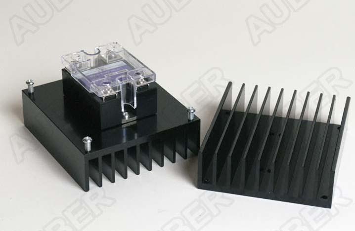
1 ea. 25A SSR Item #: MGR-1D4825 $9.95
1 ea. Thermal Pad for Single Phase SSR Item #: SI-PAD $0.99
1 ea. HeaterMeter 3D Printed Case with Defects Item #: SD-HMCase $16.00
1 ea. External Mount Heat Sink for 25A SSR Item #: HS25ET $12.50
1 ea. HeaterMeter for BBQ Control $228.85
Item #: HeaterMeter
HeaterMeter Bare Board - Four sensor ports (1 x TC, 3 x thermistor), Blue
HeaterMeter Accessories - Output Cable (Ethernet male to HM, Female 5.5mm end to SSR, needs to be paired with another wire bought separately)
HeaterMeter Accessories - Raspberry Pi (Model B)
HeaterMeter Accessories - 8GB SD Card
***DO NOT INCLUDE, BUY EDIMAX FROM AMAZON - HeaterMeter Accessories - Wireless USB Adapter
HeaterMeter Probes - K Type ThermoCouple w/Alligator Clip (TC-K6A)
(bought 3 ET-733 maverick hybrid probes cheaper on amazon)
Blower Option - None
Blower Adapter Option - None
Power Adapter Option - None
Got scratch and dent case
(Wifi Adapter that is supported and cheaper. Get this one!!!!)
Edimax EW-7811Un 150Mbps 11n Wi-Fi USB Adapter, Nano Size Lets You Plug it and Forget it, Ideal for Raspberry Pi / Pi2, Supports Windows, Mac OS, Linux (Black/Gold)
Sold by: Amazon
$8.99
(Pairs with HM Output cable!!!! - Pigtail wire for control signal to the SSR, needs to connect to another wire that comes out of the HeterMeter, so is a combo)
1pc 59" 5.5 mm x 2.5 mm Barrel DC Power Plug Connector CCTV Arduino 5.5x2.5 12V
US $4.99
Sold by: Ebay
(Metal Controller Project Box that has plenty of space, is solid, and comes with a ground screw plus hole setup)
Hoffman ASG8X8X4NK Pull Box, Screw Cover, Galvanized, 8" x 8" x 4"
Sold by: Amazon.com LLC
$13.63
(Power Chord for controller project box)
Coleman Cable 09716 14/3 SJTW Power Tool Replacement Cord, 6-Foot
Sold by: Amazon.com LLC
Add-on Item
$6.55
(On/Off Switch, I went above and beyond for a 100 amp switch because the cheap chinese 20Amp rocker switches were melting on me)
Blue Sea Systems 7250 C-Series Toggle Single Pole
Blue Sea Systems
Sold by: Amazon.com LLC
$36.84
(MUST HAVE, Insulation Shrink Wrap for putting over connectors and any electrical wiring spots, this is a set of various sizes which is much needed)
SummitLink 415 Pcs Black Assorted Heat Shrink Tube 10 Sizes Tubing Wrap Sleeve Set Combo
Sold by: Amazon
$9.69
(Flat Crimp Tool and some connectors)
DELUXE WIRING KIT / JT&T / 6992F (with flat crimp tool!!!)
Sold by: Fry's Electronics
Price:$16.29
product/5924324
(chord relief grommit) Teenitor 24 Pcs Plastic Waterproof Adjustable 3.5 - 13mm Cable Gland Joints, PG7, PG9, PG11, PG13.5, PG16, Pack of 24
Sold by: Amazon
$8.99
(wirenuts) Gardner Bender 10-003 WireGard Screw-On Wire Connector, 22-14 AWG, Orange
Sold by: Amazon.com LLC
Add-on Item
$5.74
(Maverick Probes)
Maverick Et732 Genuine Replacement 6 Foot Hybrid Probe - 2 pack
Sold by: Amazon
$29.99
Maverick ET733 Genuine Replacement 6 Foot Hybrid Probe Can Be Used As Food and Smoker Probe
Sold by: Amazon
$19.95
(Fuse Holder)
uxcell AC 125V/15A 250V/10A Screw Cap Panel Mounted 5 x 20mm Fuse Holder Black 5 Pcs
Sold by: Amazon
$6.19
(Fuses)
Bussmann GMA-15A 15 Amp Glass Fast Acting Cartridge Fuse, 125V UL Listed, 5-Pack
Sold by: Amazon
$5.98
(Female Spades for Fuse Holder and Outlet sizes which are odd sizes)
SOLOOP 280Pcs Assorted F/M Crimp Connectors Spade Terminal Insulated Electrical Wire Connector Kit Set
Sold by: Amazon
$12.99
(Panel Box Power Socket/Outlets)
10 Pcs US 3 Pins Power Socket Plug Black AC 125V 15A
Sold by: Amazon
$5.72
(12V 3amp Adapter plug - MUST HAVE 3amp plug!!!)
Eleidgs 12v 3a Plug Power Supply 5.5 x 2.5 / 2.1mm + 5.5 x 2.1mm DC 12V Female Power Plug Adapter Plug Cable Plug + 1 Meter DC Male to Female Power Cord
Sold by: Amazon
$8.99
(Extension chord that can support the amps needed to be pulled over the length of the chord, 25feet)
Bayco SL-752L 25' OSHA NRTL Compliant Extension Cord w/Single Lighted Outlet - 15amp
Sold by: Amazon.com LLC
$11.53
Extra 14 AWG Wiring, about 9-12 feet shoudl work.
Heatgun for shrinking insulation (I carefully used a Butane BBQ lighter hahaha)
Wire cutters, Needle Nose Pliers, Phillips Screw Driver, Dremel rotary tool with Metal Cutting Wheels, Universal Bit 1/4 to 1-3/8 inch, regular drill bits, zip ties, etc.)
![DSC_0234[1].JPG](/media/dsc_0234-1-jpg.527258/full?d=1507244861)
![DSC_0251[1].JPG](/media/dsc_0251-1-jpg.527257/full?d=1507244861)
![DSC_0254[1].JPG](/media/dsc_0254-1-jpg.527255/full?d=1507244861)
![DSC_0233[1].JPG](/media/dsc_0233-1-jpg.527256/full?d=1507244861)
![DSC_0247[1].JPG](/media/dsc_0247-1-jpg.527254/full?d=1507244861)
![DSC_0241[1].JPG](/media/dsc_0241-1-jpg.527226/full?d=1507244861)
![DSC_0239[1].JPG](/media/dsc_0239-1-jpg.537253/full?d=1507248245)
![DSC_0242[1].JPG](/media/dsc_0242-1-jpg.537254/full?d=1507248245)
I need to seal up the extra space around the new switch that does not melt below.
![DSC_0351[1].JPG](/media/dsc_0351-1-jpg.537255/full?d=1507248245)
![DSC_0352[1].JPG](/media/dsc_0352-1-jpg.537256/full?d=1507248245)
![DSC_0344[1].JPG](/media/dsc_0344-1-jpg.537260/full?d=1507248245)
![DSC_0349[1].JPG](/media/dsc_0349-1-jpg.537261/full?d=1507248245)
Last edited:

![DSC_0258[1].JPG](/media/dsc_0258-1-jpg.528448/full?d=1507244980)
![DSC_0302[1].JPG](/media/dsc_0302-1-jpg.528632/full?d=1507244980)