Telemachus
Fire Starter
- Jan 11, 2018
- 38
- 2
I understand completely.
My heater meter got ordered yesterday so hopefully I will get to start tinkering by the end of the week.
My plan is to use the signal that goes to the servo control but modify the code so that it is a constant on or off and not PWM. Or I might use an unused pan on the AVR micro controller and add on another hook up for the MES leaving the other connections if I ever need them for a different smoker.
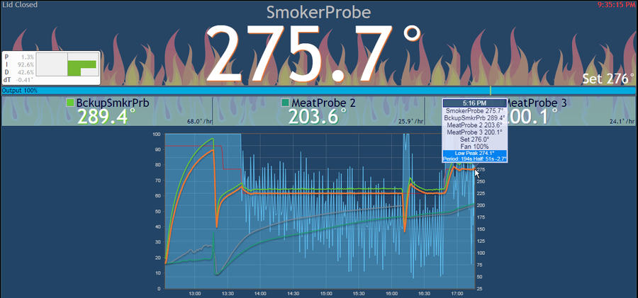
Looking at your setup on average do you have any idea how often the solid state relay is toggling on and off during a given minute?
If it is in a constant cycle of on off on off then yes and SSR makes a lot more sense.
If it is switching every 5 seconds or even less frequently than a mechanical relay should be able to hold up for quite some time.
My heater meter got ordered yesterday so hopefully I will get to start tinkering by the end of the week.
My plan is to use the signal that goes to the servo control but modify the code so that it is a constant on or off and not PWM. Or I might use an unused pan on the AVR micro controller and add on another hook up for the MES leaving the other connections if I ever need them for a different smoker.
Looking at your setup on average do you have any idea how often the solid state relay is toggling on and off during a given minute?
If it is in a constant cycle of on off on off then yes and SSR makes a lot more sense.
If it is switching every 5 seconds or even less frequently than a mechanical relay should be able to hold up for quite some time.