PID shopping list, just looking for suggestions/help

  • Some of the links on this forum allow SMF, at no cost to you, to earn a small commission when you click through and make a purchase. Let me know if you have any questions about this.
SMF is reader-supported. When you buy through links on our site, we may earn an affiliate commission.
Here's what I have so far, I'm waiting for the fan to pit adapter, and the wire bungs for the box. And I need to pick up some screws, washers and nuts.

And an AC rocker switch, and I have heat shrink tubing.

JC in GB JC in GB

I have a comp the second week of July, and need this thing running by then .

There was no rush, as my partyQ started working again. Until last week, now it's dead again, of coarse . I'm completely over this sketchy PartyQ.

Thanks for looking.
Dan.
Word of advice, beware the plastic rocker switches that come from China, I had at least 5 of them burn up and melt down on me. Something metal and heavy duty for a switch is the way to go.
I got so fed up I started using these 40A rated $15 marine breaker switches and they never failed me :D

51Hq+jUWNgL._SX522_.jpg


Mounting is simple because it only requires drilling holes.
1 hole big enough for the red switch to stick out (see how the base of it is round).
Then 2 holes for the mounting screws which are M3 or 6-32 screws that are a pan heads 3.5mm long or a hair longer. No need to cut squares/rectangle holes into the enclosure and no worrying about a switch melting down :D
 
  • Love
Reactions: forktender
Word of advice, beware the plastic rocker switches that come from China, I had at least 5 of them burn up and melt down on me. Something metal and heavy duty for a switch is the way to go.
I got so fed up I started using these 40A rated $15 marine breaker switches and they never failed me :D

View attachment 698796

Mounting is simple because it only requires drilling holes.
1 hole big enough for the red switch to stick out (see how the base of it is round).
Then 2 holes for the mounting screws which are M3 or 6-32 screws that are a pan heads 3.5mm long or a hair longer. No need to cut squares/rectangle holes into the enclosure and no worrying about a switch melting down :D
Great advice, I'll return the cheap'o I bought on Amazon, and get a good switch at West Marine.

Thanks for the tip.
Dan.
 
  • Like
Reactions: tallbm
Word of advice, beware the plastic rocker switches that come from China, I had at least 5 of them burn up and melt down on me. Something metal and heavy duty for a switch is the way to go.
I got so fed up I started using these 40A rated $15 marine breaker switches and they never failed me :D

View attachment 698796

Mounting is simple because it only requires drilling holes.
1 hole big enough for the red switch to stick out (see how the base of it is round).
Then 2 holes for the mounting screws which are M3 or 6-32 screws that are a pan heads 3.5mm long or a hair longer. No need to cut squares/rectangle holes into the enclosure and no worrying about a switch melting down :D
tallbm tallbm & JC in GB JC in GB :emoji_thumbsup:
I found a 30 amp switch that is a replacement for a welder. I'm pretty sure I should have everything I need to attempt assembling this thing by Monday.
Which will give me a few weeks to get it dialed in for my comp in mid July.

JC in GB has been a big help, I warned him that he would be dealing with the brain of a plumber. I hate electrical stuff, mainly because I don't understand it.

And thank you for the switch heads up, if I couldn't come up with a switch I was going to use an automotive blade style fuse holder and use a 35Amp fuse as the on/off "switch" until I found a heavy duty switch.
Talk about redneck engineering.:emoji_laughing:

Thanks a bunch.
Dan.
 
So I was curious about my power button I got, I went with one at auburn, it was one of the metal ones with a light and it’s push button
 
  • Like
Reactions: forktender
Word of advice, beware the plastic rocker switches that come from China, I had at least 5 of them burn up and melt down on me. Something metal and heavy duty for a switch is the way to go.
I got so fed up I started using these 40A rated $15 marine breaker switches and they never failed me :D

View attachment 698796

Mounting is simple because it only requires drilling holes.
1 hole big enough for the red switch to stick out (see how the base of it is round).
Then 2 holes for the mounting screws which are M3 or 6-32 screws that are a pan heads 3.5mm long or a hair longer. No need to cut squares/rectangle holes into the enclosure and no worrying about a switch melting down :D
This is my NC NO 110v switch but I was a little confused how to hook it up…. I thought maybe I would be the male positive and negative but then realized just the switch would be hooked up…. Now I’m wondering if I need to get a 4 prong switch thing instead of the 3 prong…. Positive prong one to SSR one to PID one for the male and one for the switch, same kind of deal with the negative…. Do I have that right?
 

Attachments

  • IMG_1592.jpeg
    IMG_1592.jpeg
    175.5 KB · Views: 24
  • IMG_1591.jpeg
    IMG_1591.jpeg
    178.5 KB · Views: 25
This is my NC NO 110v switch but I was a little confused how to hook it up…. I thought maybe I would be the male positive and negative but then realized just the switch would be hooked up…. Now I’m wondering if I need to get a 4 prong switch thing instead of the 3 prong…. Positive prong one to SSR one to PID one for the male and one for the switch, same kind of deal with the negative…. Do I have that right?
I don't have an answer atm but just saw the post. I'll see if tomorrow the 18th I can maybe help find a little info on switches like that... provided work doesn't keep me bogged down :D

I'm hoping to find some kind of a manual for that kind of switch that will give some good direction :D
 
I don't have an answer atm but just saw the post. I'll see if tomorrow the 18th I can maybe help find a little info on switches like that... provided work doesn't keep me bogged down :D

I'm hoping to find some kind of a manual for that kind of switch that will give some good direction :D

I don't have an answer atm but just saw the post. I'll see if tomorrow the 18th I can maybe help find a little info on switches like that... provided work doesn't keep me bogged down :D

I'm hoping to find some kind of a manual for that kind of switch that will give some good direction :D
I don't have an answer atm but just saw the post. I'll see if tomorrow the 18th I can maybe help find a little info on switches like that... provided work doesn't keep me bogged down :D

I'm hoping to find some kind of a manual for that kind of switch that will give some good direction :D
You’re the man! I hate electrical stuff, but I almost feel like I have the answer but the last thing I wanna do is hook it up and fail…. I’m pretty sure I’m going to just split it to a 4 prong splitter instead of the 3 prong I have now….. I’d want to hook it up NC

Here is the actual button if it helps

I'm glad you are posting here, you have a general wiring situation to consider here.
Your switch is rated for 5 Amps where I believe the MES40 pulls 10-12A.

So you cannot wire your controller where the incoming power cord wires come through the switch and split AFTER the switch or it will burn up your switch when the MES starts pulling 5A or higher, which the heating element will do.
(DO NOT WIRE LIKE THIS WITH YOUR 5A SWITCH!!!)
(diagram 1)

FkgMgVR.png


I do not recommend this approach but with a 5A power switch you could technically make things work but you would have to wire up your controller where power comes into it and then forks off before it goes to the switch, but there is are real issues with this wiring approach so again I do not recommend this, I'm just explaining things:
(diagram 2)
bqktFJS.png


Issue 1:
I believe a REX-C100 PID pulls 3A max so your 5A switch in theory could handle being wired to just shut on/off power to the PID. I still would like a 10A switch to have plenty of slop for error or poor switch components. I burned up a ton of cheap plastic Chinese 20A rocker switches when my MES should have been pulling half the amps.

BIGGER Issue 2:
This 2nd wire image has power going unchecked to your SSR. Yes, the SSR is technically a switch and is built to be heavier duty. However, should the SSR ever malfunction and get stuck in the ON position your MES will dumbly pull power until it burns up possibly causing a major fire hazard.

Why would this situation happen?
Well one, the SSR would have to malfunctions in the ON position (getting stuck there) AND two, the wiring in diagram 2 does not use your power switch to prevent/allow power from coming into the SSR. The power switch only allows prevents/allows power to go to the PID controller portion while power is always freely running to the SSR switch
In a perfectly functioning world your PID would control cutting power on/off to the MES using the SSR switch ONLY when the power switch is on. But in this imperfect world and with this wiring, it only takes the SSR malfunctioning and getting stuck in the ON position for things to go bad.


What now?

I would always err on the side of safety and caution with this stuff and just get a good beefy switch that can easily handle 20A of current and wire up like diagram 1 shows because it is the safest option AND the power switch does what a person thinks it does. It allows/prevents power from even entering the box before it gets to the PID or the SSR. If the switch burns up then no power gets in. If the switch somehow gets stuck in the on position you still have have a failure in the SSR so there is a little bit of redundancy there to lean on.

I put both these diagrams up to help explain things more easily and do not recommend going with diagram 2 as an example to follow though it technically works.
Technically we could eat raw meat but it's just safer and tastier to eat it cooked properly and seasoned well :D

I hope this flood of info helps :D
 
Last edited:
  • Love
Reactions: forktender
I'm glad you are posting here, you have a general wiring situation to consider here.
Your switch is rated for 5 Amps where I believe the MES40 pulls 10-12A.

So you cannot wire your controller where the incoming power cord wires come through the switch and split AFTER the switch or it will burn up your switch when the MES starts pulling 5A or higher, which the heating element will do.
(DO NOT WIRE LIKE THIS WITH YOUR 5A SWITCH!!!)
(diagram 1)

View attachment 699041


I do not recommend this approach but with a 5A power switch you could technically make things work but you would have to wire up your controller where power comes into it and then forks off before it goes to the switch, but there is are real issues with this wiring approach so again I do not recommend this, I'm just explaining things:
(diagram 2)
View attachment 699040

Issue 1:
I believe a REX-C100 PID pulls 3A max so your 5A switch in theory could handle being wired to just shut on/off power to the PID. I still would like a 10A switch to have plenty of slop for error or poor switch components. I burned up a ton of cheap plastic Chinese 20A rocker switches when my MES should have been pulling half the amps.

BIGGER Issue 2:
This 2nd wire image has power going unchecked to your SSR. Yes, the SSR is technically a switch and is built to be heavier duty. However, should the SSR ever malfunction and get stuck in the ON position your MES will dumbly pull power until it burns up possibly causing a major fire hazard.

Why would this situation happen?
Well one, the SSR would have to malfunctions in the ON position (getting stuck there) AND two, the wiring in diagram 2 does not use your power switch to prevent/allow power from coming into the SSR. The power switch only allows prevents/allows power to go to the PID controller portion while power is always freely running to the SSR switch
In a perfectly functioning world your PID would control cutting power on/off to the MES using the SSR switch ONLY when the power switch is on. But in this imperfect world and with this wiring, it only takes the SSR malfunctioning and getting stuck in the ON position for things to go bad.


What now?

I would always err on the side of safety and caution with this stuff and just get a good beefy switch that can easily handle 20A of current and wire up like diagram 1 shows because it is the safest option AND the power switch does what a person thinks it does. It allows/prevents power from even entering the box before it gets to the PID or the SSR. If the switch burns up then no power gets in. If the switch somehow gets stuck in the on position you still have have a failure in the SSR so there is a little bit of redundancy there to lean on.

I put both these diagrams up to help explain things more easily and do not recommend going with diagram 2 as an example to follow though it technically works.
Technically we could eat raw meat but it's just safer and tastier to eat it cooked properly and seasoned well :D

I hope this flood of info helps :D
Holy cow, tallbm tallbm , what a great response!!!
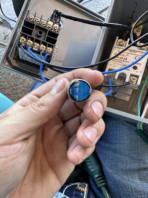
I'm almost ready to put my PID together, it will be controlling a Viper fan, to control my barrel smoker. JC in GB JC in GB has been a huge help to me, he put together a shopping list for all the main parts, plus he made me some sort of switch that looks nothing like a switch that I've ever seen. LOL!!!

It's the little white circuit board looking thing that has the zip ties on it at the bottom of this picture.
1718755580200.jpeg

I have no clue what I am doing, electrical work is my nemesis.
Being a retired Plumber/Fitter, we didn't have to work with electrical stuff ever, it's always overwhelmed me. So building this is going to be a challenge for me, I will be amazed if I can pull it off, to be honest with you.

This forum, has saved my @$$ so many times, it's amazing what complete strangers will do to help a brother out.

Thank you, guys, very much.
Dan.
:emoji_anguished::emoji_laughing:
 
Holy cow, tallbm tallbm , what a great response!!!
I'm almost ready to put my PID together, it will be controlling a Viper fan, to control my barrel smoker. JC in GB JC in GB has been a huge help to me, he put together a shopping list for all the main parts, plus he made me some sort of switch that looks nothing like a switch that I've ever seen. LOL!!!

It's the little white circuit board looking thing that has the zip ties on it at the bottom of this picture.
View attachment 699045
I have no clue what I am doing, electrical work is my nemesis.
Being a retired Plumber/Fitter, we didn't have to work with electrical stuff ever, it's always overwhelmed me. So building this is going to be a challenge for me, I will be amazed if I can pull it off, to be honest with you.

This forum, has saved my @$$ so many times, it's amazing what complete strangers will do to help a brother out.

Thank you, guys, very much.
Dan.
:emoji_anguished::emoji_laughing:
I'm glad my response made some sense hahahah.

Wow man, it looks like you are well on your way!
It takes a little bit of work and time to clear away the fog of all of this stuff once you start learning to build a PID but as the fog clears away things will be come REALLY clear when you nail down how each piece wires up and then goes together. It then turns into a tiny and understandable puzzle that when you draw it out clearly you will easily understand it all going forward :D

I'm curious as to how yours all turns out. I think the wiring will clear up for you and become the easier part soon. Then it's on to tuning that fan with your smoker. That is where I'm super curious because those settings may end up unique to your smoker vs the wiring being the same for every blower fan PID build :D
 
  • Like
Reactions: forktender
SmokingMeatForums.com is reader supported and as an Amazon Associate, we may earn commissions from qualifying purchases.

Hot Threads

Clicky