Lately I've seen a number of posts about guys wanting to rewire their MES. I had wanted to post a quick and simple guide for those out there that are curious or those that simply need to rewire but need a little assistance. Well here goes.
Disclaimer: When messing with electrical equipment it is best to consult a local electrical professional to ensure things are done correctly. Be safe and use caution. I am not an electrician and with many things you hear or read, it is your responsibility to verify the information's validity and ensure you and others are safe.
Ok now on to rewiring info :)
Smoker Referenced Below:
Quick Explanation of the Process:
The rewire is actually very simple and does NOT require removing the back of the MES. What is being done is the following:
IMPORTANT: If you plug the rewired MES into the wall there is NOTHING to control the electricity to the element. If plugged in, the MES will simply just suck electricity and heat up as a dumb circuit. This is why a 3rd party controller like a PID controller is needed.
The PID controller will control the on/off flow of electricity to the heating element according to the set temperature and the temp the PID controller is reading with a probe from within the smoker.
Simple Rewire Steps:
The process should really take between 30 minutes and 2 hours based on how you work, preperation, and confidence/comfort level with the tools and the process.
Additional Rewire Considerations:
This post is simply showing how to rewire for a 3d party controller to be used, BUT it does not address some week points of the MES wiring. I will note some improvements that should be considered because they are common issues with the MES that you will likely run into an need to fix at some point.
Disclaimer: When messing with electrical equipment it is best to consult a local electrical professional to ensure things are done correctly. Be safe and use caution. I am not an electrician and with many things you hear or read, it is your responsibility to verify the information's validity and ensure you and others are safe.
Ok now on to rewiring info :)
Smoker Referenced Below:
- MES 40 Gen1
- A strong back or a 2nd body to help pick up the smoker and set on a table to be worked on
- Waist High Table - to put the smoker onto
- Needle Nose Plyers
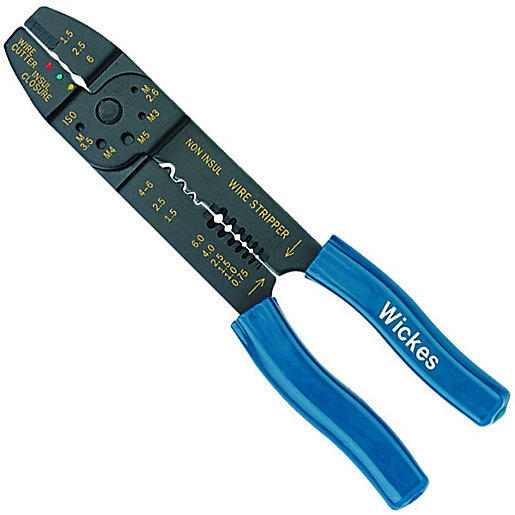
- Wire Crimping Tool - one that crimps, strips, and cuts wires
- 14-16 AWG Butt Connectors, or Wire Nuts
- Drill
- 1/8" Drill Bit that can drill metal - to drill out circuit board rivets
- #12 - 1" self tapping Sheet Metal Screws/Fastener to refasten circuit board panel back on after rivets are removed. 3/4" long may also be good for this one panel but MAY be a little short. I used 3/4" because that is what I used when pulled the back off my MES
- Drill Bit to drive the sheet metal screws (I used hex head fasteners but you may find hex + phillips head)
- Masking Tape/Electrical Tape - some kind of tape that can be used to mark a wire. U need no more than 1 inch worth
Quick Explanation of the Process:
The rewire is actually very simple and does NOT require removing the back of the MES. What is being done is the following:
- Take existing MES wiring and disconnecting it from the MES circuit board the controller is connected to
- Connect Hot wire that comes from MES plug, to Hot wire that leads to the safety Roll out Limit Switch & Heating Element
- Connect the Neutral wire that comes from the MES plug, to the Neutral wire that leads to the Heating element
- Done!
IMPORTANT: If you plug the rewired MES into the wall there is NOTHING to control the electricity to the element. If plugged in, the MES will simply just suck electricity and heat up as a dumb circuit. This is why a 3rd party controller like a PID controller is needed.
The PID controller will control the on/off flow of electricity to the heating element according to the set temperature and the temp the PID controller is reading with a probe from within the smoker.
Simple Rewire Steps:
The process should really take between 30 minutes and 2 hours based on how you work, preperation, and confidence/comfort level with the tools and the process.
- UNPLUG the MES!!!!
- Get the MES up on a table laying flat on it's back or on the front. If you lay it on the front (what I did) be sure not to break the glass window in the door... just use caution
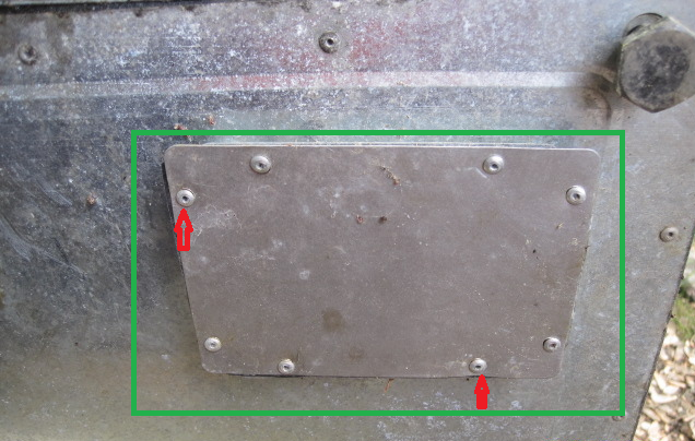
- Using the 1/8" drill bit and a drill, drill out the rivets on the bottom panel of the MES.
The bottom panel is identified by the green square, everything outside of the green square is irrelevant for this step.
The red arrows identify some rivets on the PANEL. ONLY drill out the panel rivets inside the green square, NOT the rivets outside the green square.
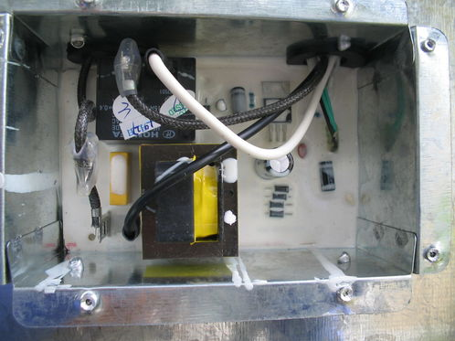
- You should see an image similar to the one below but it may be slightly different. Don't worry if it is slightly different because we will be able to easily identify the wires.
- Use your hand or the Needle Nose Plyers to disconnect the wires listed below:
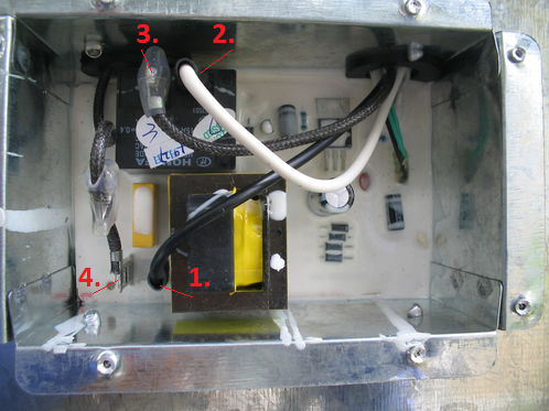
- Plug Hot Wire - Smooth Black color wire
- Plug Neutral Wire - Smooth White color wire
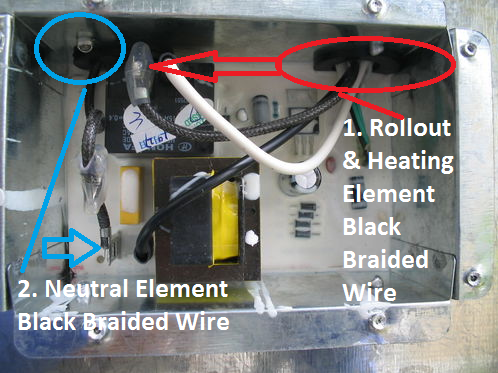
- Rollout Limit Switch & Heating Element Hot Wire - Black Braided wire
- Heating Element Neutral Wire - Black Braided wire - yes looks just like wire #3
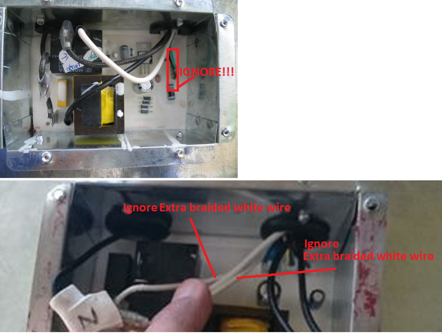
- IMPORTANT: Ignore any other tiny wires that may come out of the upper right hole of the compartment. These can be any color (black, green, white, white braided wire, etc.). They will be noticeably thinner than the real wires!
- Identify and use a piece of tape Label the black braided wires:
- Heating Element NEUTRAL Black Braided wire - Comes out of upper LEFT hole
- Rollout Limit Switch & Heating Element HOT Black Braided wire comes out of the upper RIGHT hole
The key here is to identify the hole that the wire comes out of. Use a piece of tape to flag the wires for quick identification. If you accidentally splice the wires it should be OK and all should still work safely and fine. The thing is the wiring is not TECHNICALLY accurate which may lead to some confusion about which wire goes where.
- Cut and splice wires together. Use butt connectors, wire nuts, or any electrical connectors to splice the wires. JUST BE SURE that the connections are tight!!! You want no wiggle between the connection because that causes resistance and resistance causes heat and that will burn up the wire, wiring, etc. which is bad!
- Connect wires #1 and #3. Notice they should both come out of the upper right hole/port.
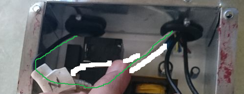
- Connect wires #2 and #4. Notice the white wire comes out of the upper right hole/port and the black braided wire comes out of the upper left hole/port. The pic is bad so I tried to erase extra wires and used a Green line to trace the wire and connections. I hope it gives the proper visual.
- Connect wires #1 and #3. Notice they should both come out of the upper right hole/port.
- When all wired up it should look like the image below:
- Use the sheet metal screws to fasten the panel back on through the rivet holes.
- Safely put the smoker back on the ground
- Open the smoker door and plug in the MES to the wall outlet. You should feel that it is heating and if you leave it on long enough you will see the element start turning color showing heat.

![DSC_0303[1].JPG](/media/dsc_0303-1-jpg.528634/full?d=1507244980)
![DSC_0302[1].JPG](/media/dsc_0302-1-jpg.528632/full?d=1507244980)
Additional Rewire Considerations:
This post is simply showing how to rewire for a 3d party controller to be used, BUT it does not address some week points of the MES wiring. I will note some improvements that should be considered because they are common issues with the MES that you will likely run into an need to fix at some point.
- Replace the Heating Element connectors with Hi Temp Stainless Steel female spade connectors - the MES uses poor electrical connectors on the wires that connect to the heating element. They don't seem to be able to stand up to the heat of the element very well and corrode easily. Mine showed signs of corrosion after 3 months of use!!! Google the following connectors as good replacement options:
Supco T1111c (typical female spade), or Supco T1113c (flag style female spade)
Again, be sure the connectors are on completely and are crimped complete! You want NO wiggle. Keep working until you get the proper connection.
- Replace the Safety Rollout Limit Switch connectors with Hi Temp Stainless Steel female spade connectors - as stated above the connectors that MES uses are poor and corrode easily. The connectors here suffere the same issue.
The big issue is that most MES smokers do not have a panel to access the rollout limit switch. In this case, you must remove the back of the MES to get to the rollout limit switch- Consider cutting and creating a panel to access this switch in the future
- The rollout limit switch is a little delicate so if you happen to damage it go to Amazon and search for: KSD301 for replacement switches should you knock a tab loose or bend it or damage it in any way.
Again, be sure the connectors are on completely and are crimped complete! You want NO wiggle. Keep working until you get the proper connection.


