Navigation
Install the app
How to install the app on iOS
Follow along with the video below to see how to install our site as a web app on your home screen.
Note: This feature may not be available in some browsers.
More options
Style variation
-
Some of the links on this forum allow SMF, at no cost to you, to earn a small commission when you click through and make a purchase. Let me know if you have any questions about this.
You are using an out of date browser. It may not display this or other websites correctly.
You should upgrade or use an alternative browser.
You should upgrade or use an alternative browser.
MES Rewire Simple Guide - No Back Removal Needed!!!
- Thread starter tallbm
- Start date
SmokingMeatForums.com is reader supported and as an Amazon Associate, we may earn commissions from qualifying purchases.
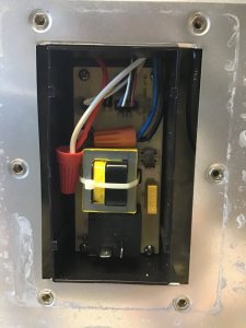
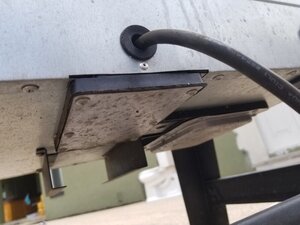
@tallbm I’m hoping you can help me with my wire situation. I have a newer gen smoker and after removing 6 screws (it’s like they made it easier on this gen to access the wiring because they knew it would need to be accessed in the future) I’m faced with the pic below. It looks as like all wires are braided and they are connected with rubber “boots”. I’m not really sure how to attack this one?
Attachments
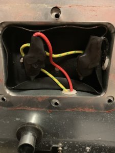
That looks like the back
To do the re wire you need to access the bottom .
To do the re wire you need to access the bottom .
Make sure you un plug the smoker . No offense , I just have to say it . To be sure .
Maybe obvious to the more electronic savvy but I need to ask anyway. On my Gen 1 I have done the re-wire and am running through an Auber PID. I have also removed the useless internal light so now the stock clamshell controller does nothing other than take up space. I'd like to just be rid of it and make a stainless or aluminum cap to cover the holes where the controller wires come through the top.
View attachment 399066
View attachment 399067
Finally to the question: Can I just snip the wires to the controller and be done with it, or are they still doing something (like completing a circuit or something)?
Since the bottom circuit board has been bypassed and the wires at the top feed into the circuit board, you are safe to cut the wires at the top and tuck them in. They are getting no power with the rewire done like the post identifies. Cover away! :)
Can I assume this to be true?
My two braided bk wires come out of the same location but I can tell from where the connect witch wires they are.......right?
Technically you should be able to just splice either black braided wire to the smooth hot wore and then splice the other black braided wire to the smooth neutral wire (smooth wires are from the plug). I don't believe the heating element cares which side it is receiving the hot vs neutral from.
If you want to figure out which braided wire is officially the hot vs the neutral of the braided wires, you would need to disconnect the braided wires from the circuit board and the heating element and do the continuity checks with a cheap multimeter (that has continuity setting) like the steps in the post identify. That will find the "official" braided hot and neutral wires.... but again I don't think the heating element cares and the circuit is pretty dumb so as long as it has the hot and neutral going to the heating element I don't think it technically matters. This does not apply with more complex electrical devices. Like I wouldn't chance swapping the smooth hot and neutral on the circuit board and hope everything with the stock MES works lol. That might fry something along the way. Our rewire is a super simple and dumb circuit so we should be good if we swap sides with the wiring :)
@tallbm I’m hoping you can help me with my wire situation. I have a newer gen smoker and after removing 6 screws (it’s like they made it easier on this gen to access the wiring because they knew it would need to be accessed in the future) I’m faced with the pic below. It looks as like all wires are braided and they are connected with rubber “boots”. I’m not really sure how to attack this one?
@chopsaw has you covered. You removed the heating element panel. The circuit board panel is on the under-side of the MES.
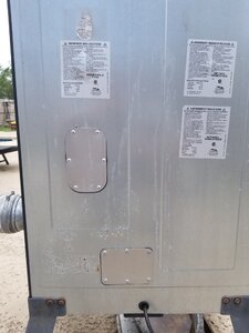
If you are lucky there is another panel on the back of your MES about half way up. Either in the center of the MES or on the right hand side. That panel takes you to the safety rollout limit switch. If you don't have that extra panel then when the day comes that your MES craps out on you after this rewire it is likely because the connectors at the heating element have burned out or the connectors the safety rollout limit switch have burned out.
In those cases the fixes are simple, just replace with hi temp stainless connectors but the complexity is that if the connector or switch burns up on you AND you don't have that extra panel, you would have to take the back off the MES to get to the switch. That is not very difficult but is a little more time consuming then just having a panel built in... I made a panel for mys witch and it has come in super handy since I have burned up 3 safety rollout limit switches due to being too rough with them during installation hahahaha.
Get some of these connectors and have them on hand for when the crappy stock MES connectors burn up on you... they will:
Also get these EXACT safety rollout limit switches in case you have to replace the existing one (or any you may ruin while replacing a burned up one like I did lol):
Have those items on hand and after the rewire with a PID you can keep your MES going until a tornado whisks it away :D
@tallbm
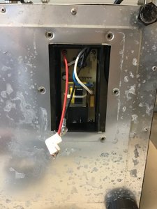
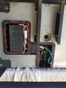
I am working on my rewire this morning. Pic below is what I am working with. I’m trying to match my wires to yours from your walkthrough (which has been very helpful!).
I have only removed the black smooth wire and red braided wire so far. These were connected to the black plug (black wire plugged into the left side, red plugged into the right side).
If I had to guess:
My black smooth wire = #1 in your walkthrough
My white smooth wire = #2 in your walkthrough
My red braided wire = #4 in your walkthrough
My blue braided wire = #3 in your walkthrough
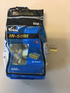
Also- in terms of making the connection do you think the wire connectors pictured will work?
Pic of wires in smoker:
Pic of connectors:
I am working on my rewire this morning. Pic below is what I am working with. I’m trying to match my wires to yours from your walkthrough (which has been very helpful!).
I have only removed the black smooth wire and red braided wire so far. These were connected to the black plug (black wire plugged into the left side, red plugged into the right side).
If I had to guess:
My black smooth wire = #1 in your walkthrough
My white smooth wire = #2 in your walkthrough
My red braided wire = #4 in your walkthrough
My blue braided wire = #3 in your walkthrough
Also- in terms of making the connection do you think the wire connectors pictured will work?
Pic of wires in smoker:
Pic of connectors:
Attachments
Last edited:
Some people terminate the red to smooth black like you have because they were terminated at the black cube relay where VAC circuit opens and closes and leave the white and blue wires terminated at the circuit board. I wanted to not use any MB chinese aluminum connectors and cut and wire nutted in your case black to red and blue to white. Mine are two braided black as in the element access area. Mine are reversed but it doesnt matter with VAC and a heating element and not a motor. As long as the braided colored are with a white or black and not together and the white and black aren't together.@tallbm
I am working on my rewrite this morning. Pic below is what I am working with. I’m trying to match my wires to yours from your walkthrough (which has been very helpful!).
I have only removed the black smooth wire and red braided wire so far. These were connected to the black plug (black wire plugged into the left side, red plugged into the right side).
If I had to guess:
My black smooth wire = #1 in your walkthrough
My white smooth wire = #2 in your walkthrough
My red braided wire = #4 in your walkthrough
My blue braided wire = #3 in your walkthrough
Also- in terms of making the connection do you think the wire connectors pictured will work?
Pic of wires in smoker:
Pic of connectors:
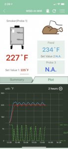
Thanks @dr k. I completed the rewire, hooked up the Auber, and ran a test drive. Everything is working as it should!
Attachments
@tallbm
I am working on my rewire this morning. Pic below is what I am working with. I’m trying to match my wires to yours from your walkthrough (which has been very helpful!).
I have only removed the black smooth wire and red braided wire so far. These were connected to the black plug (black wire plugged into the left side, red plugged into the right side).
If I had to guess:
My black smooth wire = #1 in your walkthrough
My white smooth wire = #2 in your walkthrough
My red braided wire = #4 in your walkthrough
My blue braided wire = #3 in your walkthrough
Also- in terms of making the connection do you think the wire connectors pictured will work?
Pic of wires in smoker:
Pic of connectors:
@dr k has you well covered and as you have found out you are good to go! :)
I wouldn't worry about using wire nuts there. No real heat gets down to the circuit board as far as I could ever tell so plastic wire nuts should not be an issue. Great work!
I have been having trouble with my Auber Instruments Controller, their tech support said not to leave the controller on top of the smoker. There seems to be a heat issue with them,
If you can put your PID on a few 2x4s or on something between the top of the MES and the bottom of your auber that would be very telling as to what may be happening with your unit.
If I remember correctly you are running the 1200watt max capacity unit on an MES40 (1200watt MES).
It would be good to get that separation and see if it's the unit itself vs any heat transfer from the MES to the unit.
Let us know when you get a few smokes going for like 6+ hours. The results with your setup will be super helpful to log and know.

martcrna10
Newbie
- Aug 10, 2016
- 16
- 13
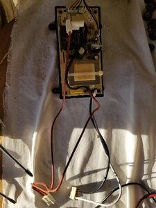
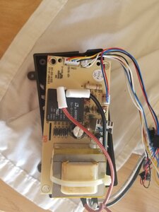
Sorry for including so many pics, just trying to give the best idea of what I'm looking at.
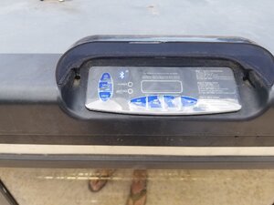
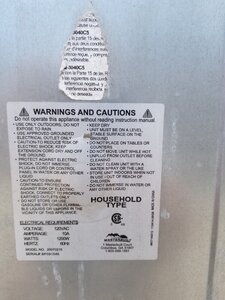
I'm pretty sure this is a Gen 2.5 MRS 40. My electronic controller has failed again and since they don't make replacements anymore I figured I would run it with an Auber controller.
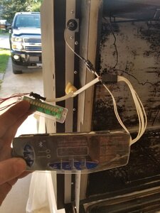
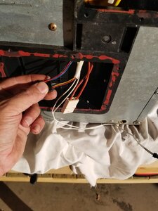
As you can see in the pics there are several wire harnesses coming from the controller. 1 was connected to the meat probe which I have removed, a 3-wire harness runs a LED light that shines over the door (which I don't care about losing) and a 5-wire harness that runs the OEM controller.
On the bottom end where the second circuit board is that includes the AC adapter and relay you'll see the other end of the harness for the LED light, OEM controller, red braided wires that comes from the heating element, smooth black and white wires coming from the power cord & 2 braided white wires that I believe are coming from the temperature switch control (but not positive).
I need guidance from here, do I just unplug the OEM controller? Do I need to bypass this second circuit board? If so, what do I need to do?
Thanks for any help!!
Matt
I'm pretty sure this is a Gen 2.5 MRS 40. My electronic controller has failed again and since they don't make replacements anymore I figured I would run it with an Auber controller.
As you can see in the pics there are several wire harnesses coming from the controller. 1 was connected to the meat probe which I have removed, a 3-wire harness runs a LED light that shines over the door (which I don't care about losing) and a 5-wire harness that runs the OEM controller.
On the bottom end where the second circuit board is that includes the AC adapter and relay you'll see the other end of the harness for the LED light, OEM controller, red braided wires that comes from the heating element, smooth black and white wires coming from the power cord & 2 braided white wires that I believe are coming from the temperature switch control (but not positive).
I need guidance from here, do I just unplug the OEM controller? Do I need to bypass this second circuit board? If so, what do I need to do?
Thanks for any help!!
Matt
Attachments
-
 20200416_142550.jpg105.2 KB · Views: 128
 -
 20200416_142639.jpg92.3 KB · Views: 134
 -
 20200416_163311.jpg127.4 KB · Views: 133
 -
 20200416_181746.jpg125.2 KB · Views: 140
 -
 20200416_142510.jpg152.5 KB · Views: 132
 -
 20200416_184515.jpg116.5 KB · Views: 135
 -
 20200416_142516.jpg87.8 KB · Views: 134
 -
 20200416_184737.jpg95.3 KB · Views: 125
 -
 20200416_142537.jpg150.3 KB · Views: 137
 -
 20200416_185009.jpg117.5 KB · Views: 129
 -
 20200416_173245.jpg95.4 KB · Views: 157
 -
 20200416_173345.jpg84.8 KB · Views: 151
Hi there and welcome!Sorry for including so many pics, just trying to give the best idea of what I'm looking at.
I'm pretty sure this is a Gen 2.5 MRS 40. My electronic controller has failed again and since they don't make replacements anymore I figured I would run it with an Auber controller.
As you can see in the pics there are several wire harnesses coming from the controller. 1 was connected to the meat probe which I have removed, a 3-wire harness runs a LED light that shines over the door (which I don't care about losing) and a 5-wire harness that runs the OEM controller.
On the bottom end where the second circuit board is that includes the AC adapter and relay you'll see the other end of the harness for the LED light, OEM controller, red braided wires that comes from the heating element, smooth black and white wires coming from the power cord & 2 braided white wires that I believe are coming from the temperature switch control (but not positive).
I need guidance from here, do I just unplug the OEM controller? Do I need to bypass this second circuit board? If so, what do I need to do?
Thanks for any help!!
Matt
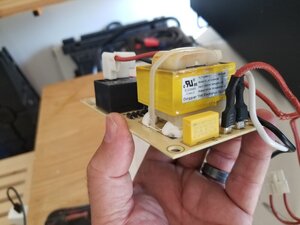
Wow it looks like they might have made it easy to bypass their circuit board with the new clips.
In short all ou need to do is connect the Black and White wire clip from the plug to the double braided Red Wire clip that runs up into the unit, NOT the clip for the red wires that run to the circuit bard.
At that point you could clip all the little thin wires that run to the light and the controller on top and then toss out the circuit board. Simple as that!
The older models there are no clips and you basically have to cut the ends off the red braided wires on the circuit board and the ends off the black and white wire on the circuit board that run to the cord. U splice black to red, and white to red and u are done!
Now you can just fit the clips together provided they fit, if not you cut and splice the old way to red to black, and red to white, and bypass the circuit board and toss the circuit board!
Super simple :)
Let me know if this makes sense :)
martcrna10
Newbie
- Aug 10, 2016
- 16
- 13
Yep, makes perfect sense, thanks for the info.
I'll take pics as I do the mods and post here when everything is done and running so others in the future will have pics of the mods for this model MES.
Thanks again!
Matt
I'll take pics as I do the mods and post here when everything is done and running so others in the future will have pics of the mods for this model MES.
Thanks again!
Matt
Definitely post back to share the info so others can learn from your model.Yep, makes perfect sense, thanks for the info.
I'll take pics as I do the mods and post here when everything is done and running so others in the future will have pics of the mods for this model MES.
Thanks again!
Matt
I'm looking forward to seeing how it all comes out :)
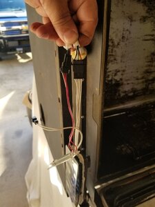
Your last pic when you blow it up shows a red braided insulation that looks frayed at your pinky finger. Cut and wire nut the red and white wires with black tip insulation at your pinky and the black and red wires connected to the black cube relay at your thumb and done. Doesn't matter. A red wire needs to be terminated to the black hot and the other red to the white neutral. Mine is backwards. I wanted to get rid on those crap lugs. If that red is damaged and may have broken strands of wire inside the insulation you may have to cut there and terminate backwards like mine, depending on how much lead wire you have to work with.
martcrna10
Newbie
- Aug 10, 2016
- 16
- 13
Thanks for pointing that out Dr K, I saw that frayed bit of insulation as well. Luckily I have a decent length of wire to work with so cutting behind the frayed part shouldn't be a problem.Your last pic when you blow it up shows a red braided insulation that looks frayed at your pinky finger. Cut and wire nut the red and white wires with black tip insulation at your pinky and the black and red wires connected to the black cube relay at your thumb and done. Doesn't matter. A red wire needs to be terminated to the black hot and the other red to the white neutral. Mine is backwards. I wanted to get rid on those crap lugs. If that red is damaged and may have broken strands of wire inside the insulation you may have to cut there and terminate backwards like mine, depending on how much lead wire you have to work with. I also have some insulated butt connectors I can use for splicing the new connections.
martcrna10
Newbie
- Aug 10, 2016
- 16
- 13
How are you liking the WSD-1500H-W Auber controller? That's the one I'm looking at for mine as well.Thanks @dr k. I completed the rewire, hooked up the Auber, and ran a test drive. Everything is working as it should!
Hi there and welcome!
Wow it looks like they might have made it easy to bypass their circuit board with the new clips.
In short all ou need to do is connect the Black and White wire clip from the plug to the double braided Red Wire clip that runs up into the unit, NOT the clip for the red wires that run to the circuit bard.
At that point you could clip all the little thin wires that run to the light and the controller on top and then toss out the circuit board. Simple as that!
The older models there are no clips and you basically have to cut the ends off the red braided wires on the circuit board and the ends off the black and white wire on the circuit board that run to the cord. U splice black to red, and white to red and u are done!
Now you can just fit the clips together provided they fit, if not you cut and splice the old way to red to black, and red to white, and bypass the circuit board and toss the circuit board!
Super simple :)
Let me know if this makes sense :)
I just wanted to chime in... my Gen 2 MES died last year and control boards are nonexistent so I decided to go the PID route. When I opened it up, the wiring looked nothing like the OPs and I thought I was in trouble - I am good with my hands, but technically ignorant. When I saw martcrn's pics I knew I had the same style of wiring. I went inside, had a beer (thinking I was going to have to tear apart the circuit box with its security screws), then came back to look at it. I literally just had to unclip the power in and power out of the circuit box and clip them together! No splicing, no cutting, nothing! I plugged my MES into my PID and it is up and running.
THANK YOU ALL!!!
Last edited:

SmokingMeatForums.com is reader supported and as an Amazon Associate, we may earn commissions from qualifying purchases.
Similar threads
- Replies
- 2
- Views
- 230
- Replies
- 27
- Views
- 2K
- Replies
- 23
- Views
- 837
SmokingMeatForums.com is reader supported and as an Amazon Associate, we may earn commissions from qualifying purchases.

SmokingMeatForums.com is a community of barbecue and outdoor cooking enthusiasts dedicated to smoking meat.
© 2004-2026 SmokingMeatForums.com