MES 40 gen 2.5 pid wiring

  • Some of the links on this forum allow SMF, at no cost to you, to earn a small commission when you click through and make a purchase. Let me know if you have any questions about this.
SMF is reader-supported. When you buy through links on our site, we may earn an affiliate commission.

okiecat

Smoke Blower
Original poster
Dec 3, 2011
83
16
SW Oklahoma
Just bought a Cabelas sportsman elite 40. Also purchased a Auber WS-1510 ELPM. Read the tutorial by Tallbm on wiring Gen 1. My question is my wires are different They all come from same place and I have 2 Copper braided looking wires but I don't know which one would be #4 or #3 as in the gen 1 Blk Braided ones. It has the white (neutral), and the blk smooth. took pics but don't have a clue how to load..
 
Just bought a Cabelas sportsman elite 40. Also purchased a Auber WS-1510 ELPM. Read the tutorial by Tallbm on wiring Gen 1. My question is my wires are different They all come from same place and I have 2 Copper braided looking wires but I don't know which one would be #4 or #3 as in the gen 1 Blk Braided ones. It has the white (neutral), and the blk smooth. took pics but don't have a clue how to load..

Without pics it will be hard to walk you through the wiring. I only use a computer to access the site so I cant exactly walk you through uploading pics from your phone using the mobile app. I add my pics the old fashion way by wiring up my phone to my laptop with a USB chord and then attaching the images that way.

Technically connecting either wire [1 to 3 and 2 to 4] OR [1 to 4 and 2 to 3] should work but lets try and be as accurate as possible with the wiring which is basically a good electrical practice :)
If you don't have a Multimeter with a continuity setting then get one. With the Multimeter you can figure out which of your copper wires are #3 and #4 from the picture:
full


You will do so:
  1. by unplugging your copper wires from the circuit board (it should be somewhat comparable to the circuit board in the image above)
  2. Next unplug the connectors from the heating element
  3. Next you need access to the rollout limit switch. If you have a panel that allows you to access it then great, if not you will need to pull the back off your MES or confidently cut a panel to the switch... I suggest pulling the back off in that case and when it is pulled off you cut your panel, this will avoid cutting wires :)
  4. Using the Multimeter and the continuity setting you check your unplugged Copper braided wires from the circuit board one at a time from the unplugged copper wire end to the rollout limit switch BOTTOM connector. When the multimeter lights up and/or makes a noise you have technically found the HOT/black wire. Wrap a piece of tape around that copper wire and label it HOT
    • Now to check the copper wires one at a time from the HEATING ELEMENT side to the rollout limit switch TOP connector and when the multimeter lights up or makes a noise you have found the HOT wire for the heating element, wrap a piece of tape around it and label it HOT
    • To do a thorough check, use the multimeter to check continuity from the labeled HOT copper wire from the HEATING element end and the labeled HOT copper wire from the CIRCUIT BOARD end and the multimeter should light up and/or make a noise. This confirms that is the HOT wire and it travels from the circuit board to the rollout limit switch to the heating element
  5. Confirm the NEUTRAL wire by using the multimeter on the continuity setting to check the unlabeled copper wire end from the CIRCUIT BOARD against the unlabeled copper wire from the HEATING ELEMENT. The multimeter should light up and/or make a noise to confirm that the wires has continuity. Use a piece of tape and label both ends of this wire as NEUTRAL.
  6. NOW according to the image above the copper wire labeled HOT at the CIRCUIT BOARD end would be #3
  7. According to the image above the copper wire labeled NEUTRAL at the CIRCUIT BOARD end would be #4
  8. Now you can wire 1 & 3 together for the HOT wiring
  9. You can wire 1 & 4 together for the NEUTRAL wiring
Get your hands on a Multimeter, a $5-$10 one with a continuity setting will do the trick. I hope this helps out some.
Let me know if this makes any sense and get some pics posted as soon as possible :)
 
Last edited:
Thanks thats detailed thats also the reason I asked, I am clueless when it comes to wiring and electronics. I can do a lot of things but that is one that skipped me. I do have a multimeter but Im going to try the pics first. I like the idea of getting them of phone to my mac book. We will see how that goes.
 
Thanks thats detailed thats also the reason I asked, I am clueless when it comes to wiring and electronics. I can do a lot of things but that is one that skipped me. I do have a multimeter but Im going to try the pics first. I like the idea of getting them of phone to my mac book. We will see how that goes.


Looks like you're in good hands on that, with Tallbm.

Bear
 
i hope you can figure out the pictures... i would like to see more pics of that smoker than the one pic they have on their website that doesnt really show much. how much did you pay?
Sorry Jimmy, I got busy reading the other post I missed yours. Got the pics figured out. Will take some more tomorrow. Its on its back right now. Paid about $290 at Cabelas, that was a couple wks ago.
 
  • Like
Reactions: jimmyinsd
Looks like you're in good hands on that, with Tallbm.

Bear
Bear thanks for the vote of confidence. I think we will get him sorted out here :)

Thanks thats detailed thats also the reason I asked, I am clueless when it comes to wiring and electronics. I can do a lot of things but that is one that skipped me. I do have a multimeter but Im going to try the pics first. I like the idea of getting them of phone to my mac book. We will see how that goes.

okiecat, looks like you are getting the pics sorted out and having that multimeter handy will be super helpful!
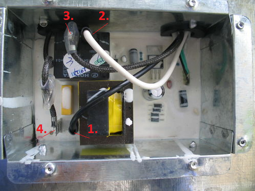
Those are good pics of the circuit board and the wires going to the circuit board.

Next, if you can get some good pics of the copper braided wires going up into the smoker from the circuit board that may help us out some.
Also a picture of the back of the smoker would help as well so we can see if you do or do not have a built in access panel to the rollout limit switch.
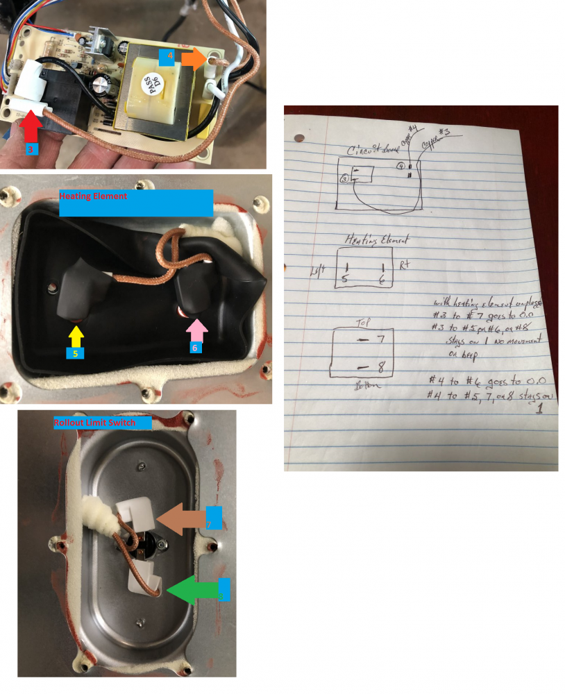
I guess pictures of the panels removed from the heating element and rollout limit switch (if it has a panel to remove) showing the wiring will be helpful as well. I would be able to download those images, mark them up, and we would be looking and talking about the exact components of your smoker in that case :)

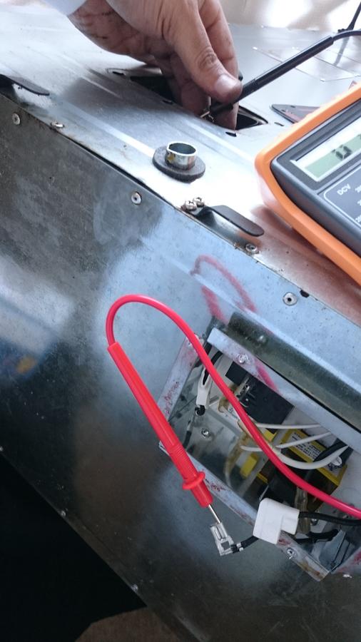
Here is a pic I have of me doing the final continuity check on the HOT wire from the circuit board to the heating element after I traced the HOT wire to the roll out limit switch and then from the rollout limit switch to the heating element wire. You have to make sure the wires are also unhooked from the heating element when doing this or you can get a false reading.
full


You are well on your way my friend and I think we can get you sorted out :)
 
Last edited:
okiecat thanks for the pic of the heating element. Is there another panel on the back of the smoker?
Also, I would need to see the wires in the area noted in the image below :)
okiecat.png
 
The wire from circuit board are all together and go thru a hole. Nothing to see to tell where there going. Will get a pic tomorrow night. Had to go to work today and tonight. The pics and diagrams you have put up help me a ton understand what I’m trying to do. Can’t work on it till Sat. Thanks again
 
Well It is good to see that the roll out limit switch (your latest pic) has an access panel, so no need to pull the back off or cut a panel yourself.

On Saturday you can simply unhook the copper braided chords from the circuit board and from the heating element.
Then you start to trace from the circuit board to the rollout limit switch then to the heating element to find the HOT wire.
The braided copper wire that that doesn't track from the circuit board to the rollout limit switch should be the neutral.

The key is to first find the braided copper wire that goes from the circuit board to rollout limit switch. Don't even start trying to trace from the circuit board to the heating element wires until you find the one that goes from the circuit board to the limit switch.

I look forward to hearing how it all turns out :)
 
Got in tonight and went to shop to try the continuity game. Well I’m a little confused so I made a diagram of what happened The numbers are just to keep track of everything.
 

Attachments

  • C8563F17-AFFE-4CFC-894A-B0895B826B31.jpeg
    C8563F17-AFFE-4CFC-894A-B0895B826B31.jpeg
    118.9 KB · Views: 41
Thanks Sarge, I was lucky enough to find my owners manual for my multi meter of 15yrs ago. If it reads 1 is that a complete circuit. When it was reading 0 it would start out like 340 and rapidly count down to 0, in a matter of seconds. Never heard a beep on either one, but I'm pretty deaf.
 
If the continuity is good, it should show 0. Same as if you touch the two probes together.. Here is a video for a thermo couple shut off:

 
Got in tonight and went to shop to try the continuity game. Well I’m a little confused so I made a diagram of what happened The numbers are just to keep track of everything.

Ok I think some progress may have been made but I am going to try and make sure we are on the same page so I put together an image made from all of your posted images to this point and I marked up the images to try and match your notes. Let me know if this is accurate and we will proceed from there.

Also just to clarify, please confirm if you unhooked the copper wires from both the heating element and the circuit board when doing your continuity checks :)
full
 
SmokingMeatForums.com is reader supported and as an Amazon Associate, we may earn commissions from qualifying purchases.

Latest posts

Hot Threads

Clicky