booboohead
Newbie
- Nov 5, 2013
- 8
- 10
I know there is a wealth of information on here and was interested to see how those that have built PID Controller using a DC-DC SSR wired there setup.
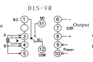
I have a Sestos D1S-VR-24 , Fotek SSR Input: DC 3-32V; Output: DC 5-60V and FAN (black and red wire)
I plan on setting it up as show in this link below (adjusting the connections to the PID based on SESTOS specifications of course)
http://www.susanminor.org/Rayeimages/pid/diagram.jpg
Some other instructions on this forum I was wondering about by a member named Gene:
1. The left hand screw #1 is you line in voltage to the SSR, the hot wire of the power cord connects to this terminal, but the hot wire also connects to the AC screw #1 on PID so you will need a short length of wire and a wire nut to join the three wires together.
The #2 screw on the SSR is the hot wire to your blower.
The #3 +(pos)screw on the SSR is connected to the +(pos) DC screw #10 on the PID
The #4 -(neg) screw on the SSR is connected to the -(neg) DC screw #9 on the PID.
2. First is your thermocouple a K type? If so the +(pos) connects to the +(pos) screw on the PID and the -(neg) to the -(neg) screw on the PID, if the polarity is reversed the PID will read in the opposite direction, example: if the temp is rising the PID will be descending, if this is the case just switch the wires, the third wire could possibly be a ground for the shielded cable and my directions say to connect it to the -(neg) only if the the PID display changes erratically.
We're not done however,
The neutral wire of the AC power cord is connected to the neutral wire of the blower and a short wire to the other AC screw #2 on the PID, with a wire nut.
Because I am using DC-DC SSR and a 12-24V DC PID what do I need to do to with the wiring? Does anything need to change? This link above seems to be a popular reference so I thought Id run it by you folks. Below is my terminal layout for my PID.
Thanks guys!
Andy

