madtownmonkey
Newbie
- May 11, 2017
- 12
- 10
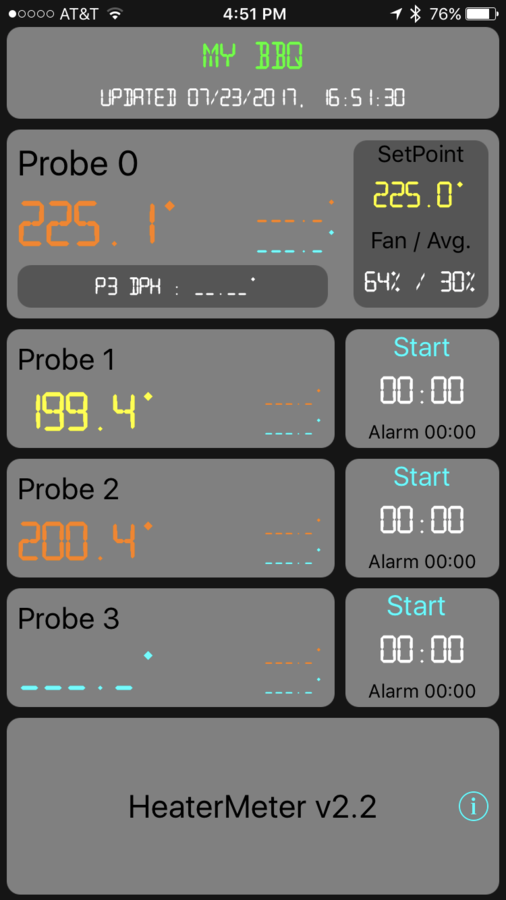
So I'll try toggle some information about how I added heater meter control to my MES 40.
I ordered some five pin connectors from amazon.
happily these turned out to exactly match the connectors used to connect the bluetooth controller to the MES.
I also ordered an adjustable voltage divider though you could easily use fixed resistors as well.
This allowed me to reduce the heater meter fan control line to 3.3 volts (which is what comes from the controller board.
I also ordered a weatherproof ethernet pass through.
to connect the heatermeter control line to the MES.
I also bought a single throw dual pole toggle switch at my local home depot.
There is a small amount of soldering involved in this project. I also used liberal amounts of heat shrink tubing.
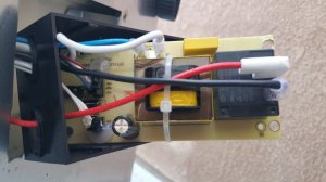
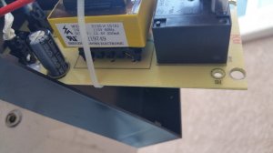
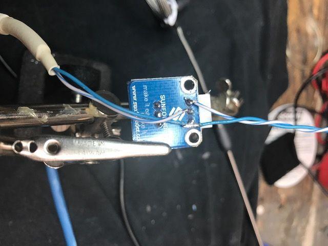
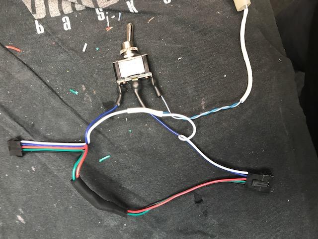
I started by butchering an ethernet cable and using just the blue (ground) and blue white (fan control signal) I soldered thereto the ground and VCC pins of the voltage divider. I also soldered another blue wire to the ground pin (to carry through to the MES) and another blue white to the output of the potentiometer as shown below
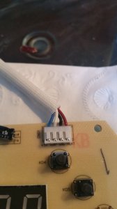
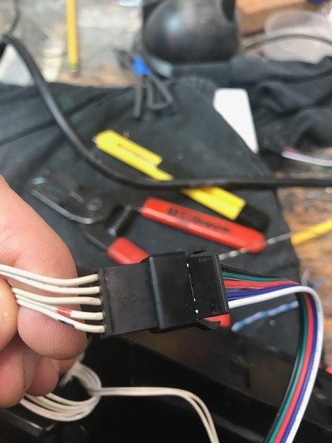
Now I started setting up the connectors. All the lines but the blue (signal) and white (signal ground) go through. The package comes with both male and female connectors so you can take one of each and solder together the black, greed and red wires. You can also solder together the white wires and solder in the blue wire from to potentiometer ground.
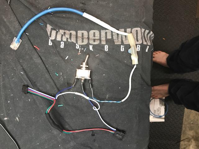
That's really all the soldering. Now you can attach the blue wire from the controller side of your go between cable to one pole of the switch and the output side to the center connector. The blue white wire from the output of the potentiometer goes to the other pole as shown below. Now you can select between on-board control and heater meter control.
Here' the final wired assembly, as you can see I put heat shrink everywhere.
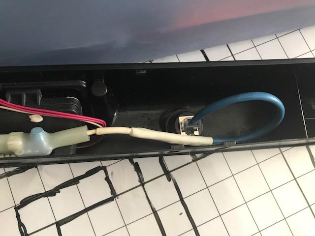
I used a stepped drill bit to drill holes in the plastic controller cover for both the switch and the ethernet pass through. Here's the pass through side (I put it on the left)
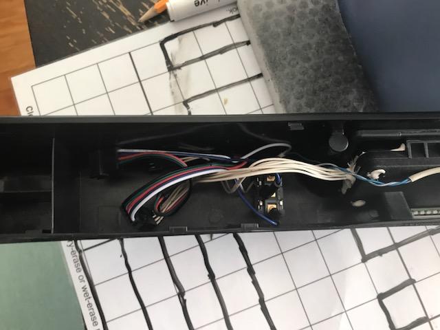
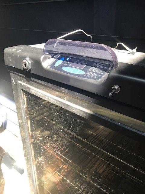
Here's the switch side. There was plenty of room for the wiring.
Here's the assembled panel on the MES. I think it looks pretty clean. Well the smoker is dirty but the install looks nice.
I think theres room for something even nicer. You could take the 5 volt line from the heater meter controller and use that to automatically detect the heater meter connection and automatically switch to heater meter control.
I ordered some five pin connectors from amazon.
happily these turned out to exactly match the connectors used to connect the bluetooth controller to the MES.
I also ordered an adjustable voltage divider though you could easily use fixed resistors as well.
This allowed me to reduce the heater meter fan control line to 3.3 volts (which is what comes from the controller board.
I also ordered a weatherproof ethernet pass through.
to connect the heatermeter control line to the MES.
I also bought a single throw dual pole toggle switch at my local home depot.
There is a small amount of soldering involved in this project. I also used liberal amounts of heat shrink tubing.
I started by butchering an ethernet cable and using just the blue (ground) and blue white (fan control signal) I soldered thereto the ground and VCC pins of the voltage divider. I also soldered another blue wire to the ground pin (to carry through to the MES) and another blue white to the output of the potentiometer as shown below
Now I started setting up the connectors. All the lines but the blue (signal) and white (signal ground) go through. The package comes with both male and female connectors so you can take one of each and solder together the black, greed and red wires. You can also solder together the white wires and solder in the blue wire from to potentiometer ground.
That's really all the soldering. Now you can attach the blue wire from the controller side of your go between cable to one pole of the switch and the output side to the center connector. The blue white wire from the output of the potentiometer goes to the other pole as shown below. Now you can select between on-board control and heater meter control.
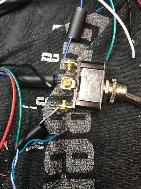
Here' the final wired assembly, as you can see I put heat shrink everywhere.
I used a stepped drill bit to drill holes in the plastic controller cover for both the switch and the ethernet pass through. Here's the pass through side (I put it on the left)
Here's the switch side. There was plenty of room for the wiring.
Here's the assembled panel on the MES. I think it looks pretty clean. Well the smoker is dirty but the install looks nice.
I think theres room for something even nicer. You could take the 5 volt line from the heater meter controller and use that to automatically detect the heater meter connection and automatically switch to heater meter control.