HeaterMeter Controller, with Wifi, and Electric Smoker (MES40) Mod in Detail

  • Some of the links on this forum allow SMF, at no cost to you, to earn a small commission when you click through and make a purchase. Let me know if you have any questions about this.
SMF is reader-supported. When you buy through links on our site, we may earn an affiliate commission.
I don't understand the role of the SSR. There is already a mechanical relay built in for the stock controller.

Does the heater meter cycle the heater element rapidly enough that you need to be worried about the built in relay blowing?

The HeaterMeter was built to control a blower fan blowing on charcoal. It does so by supplying 0-12V to the fan based on the temp in the smoker vs the set temp. Rigging it to work for an electric smoker means it would be cycling up and down through 0-12V as it deems fit so in theory it could hammer a relay.

Also I didn't have any info on the relay that was built into the MES so the SSR was the only way I knew to go.

With the SSR it will be swiched on with a signal between 3-32V. The HeaterMeter will at times feed signal to the SSR below 3V even though that won't turn on the SSR but as the temp in the MES fails to move up the HeaterMeter will increase the signal to 3V or higher which then switches the SSR on which then allows power to feed to the heating element.

This is the "hack job" or work-around that allows the HeaterMeter to work with the MES even though it wasn't initially designed that way. I could work on modifying the HeaterMeter project code to manage a Relay or an SSR but as horrible as it may sound I don't see the Return On Investment with using so much of my time to do something that only marginally improves my situation and/or meets such a small demand (that I am aware of). :)
 
I understand completely.

My heater meter got ordered yesterday so hopefully I will get to start tinkering by the end of the week.

My plan is to use the signal that goes to the servo control but modify the code so that it is a constant on or off and not PWM. Or I might use an unused pan on the AVR micro controller and add on another hook up for the MES leaving the other connections if I ever need them for a different smoker.

Looking at your setup on average do you have any idea how often the solid state relay is toggling on and off during a given minute?

If it is in a constant cycle of on off on off then yes and SSR makes a lot more sense.

If it is switching every 5 seconds or even less frequently than a mechanical relay should be able to hold up for quite some time.

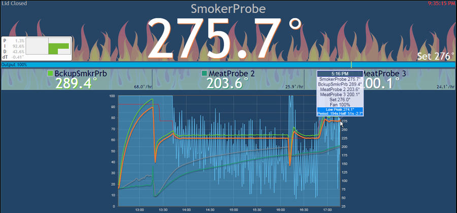
In the image below you will see in light blue some peaks and valleys during the duration of the smoke. That is the output/signal level of the "Fan" that you can measure against the Left vertical axis of the graph 0-100. Anytime that valleys are below 25% (3V) then the SSR is in an Off state. At 25%+ (3V+) then the SSR is in an On state.

I can't easily tell from the image but there shows a possibility that the signal may hammer the Relay BUT there is also lots of evidence in the image that shows that the SSR is ON for much of the smoke. I would really need to zoom in on the HeaterMeter graph and see what the signal data over time really is.

This isn't much definitive help but may give some educated guesses as to what you can expect with the signal during a smoke :)
 
Logic would have me believe the same, that 0% is 0v at 100% is 12V.

But Bryan Maryland over on ttwvb told me today that the output of the blower is actually a variable voltage output of 5V-12.1V. It never goes below 5V.

I'm not sure how your SSR is ever turning off.

Other interesting info about the duty cycle too:

https://tvwbb.com/showthread.php?72953-Blower-Output-at-Constant-3-3V&p=801666#post801666

I see you have been diving in full force :)
I'm looking over everything and it is starting to come back to me as to how it all works.

There are 2 different Fan Output settings: Pulse and Voltage.

The default is Voltage and will give a constant voltage between 5-12.1V (according to documentation).
The Pulse setting will use a continuous series of pulses. This would mean you get No/0V between pulses and 12V when the pulse is delivered.

For electric smokers (you have to dig up this info in the tvwbb forums not documentation) Bryan states that the Fan Output setting should be set to PULSE and that min, max, and startup max be set to 100%.
Interpreting the documentation (see link below) it appears that with the settings of 100%, when the PID output is 100% then the Pulse will fire at 100% Voltage output of 12V which should trigger the SSR to flip on and allow heat to move to the electric smoker heating element.

I was incorrect in thinking/stating that the PID output of 25% would give a voltage of 3V :oops: because the min/max/startup max are all at 100% and the documentation seems to state that when the PID Output is 100% then the min/max % will dictate the amount of voltage percent sent out which may be helpful for a fan but for an SSR that is triggered between 3-32V, the settings are almost irrelevant. 100% should send a 12V pulse which is well within the 3-32V range to switch On the SSR.

NOW, the min/max % may be relevant for controlling the amount of voltage you would want to send to the MES relay since it works on lower voltage. This may be a simple way to step down your Voltage and hold it at the right number :)
You would need to test this theory with with a multimeter to see what REAL percent works lol.

I'm not well versed in this area so bare with me.
As for hammering the relay, the frequency in the documentation is 490Hz or 490 pulses per second. I THINK that if you mess with Servo Pulse Duration settings that could/would increase the Pulse Width so that the relay is ON longer and would get fewer switches on/off per second or per minute. Again I'm not really sure here and what I am thinking may result in a constant ON state.
If I am thinking correctly then a duration of 10 seconds (10,000,000 micro seconds/us, the unit used in the setting) would give you 6 on's or so per minute so 12 switches on/off per minute (I think).

Do you know the number of switches the MES relay would likely be able to handle?

HeaterMeter Documentation for Fan Output: Pulse, Servo Pulse Duration, etc.: https://github.com/CapnBry/HeaterMeter/wiki/Configuration-WebUI-Documentation
 
Servo control is a different beast altogether. A servo is set up on a PWM, with 0.5-1.5 MS as the signal. That is unrelated to the blower output that we are talking about using (but you knew that...)

Yes, the only way that your relay is working at all is if you are in the pulse mode of the blower. You basically get full off (0V) or full on (12V) and your SSR input having such a wide range is taking it without a problem.

The blower cycle is set at 10 seconds in the code. The amount of time it is on is calculated by taking the PID output divided by 10. ie: 20% PID output, the relay is signaled on for 2 seconds and off for 8 seconds.

So maximum on/off over 1 minute would be 12 times.

Over 10 hours of smoking, that is 7200 toggles.

While its not as bad as the MP3 coordinated Christmas lights I once tried on a mechanical relay (it blew in a few minutes), its not ideal with a mechanical relay.

Still, it's there, and easy to access, so I'm going to use it until it blows. Then I'll replace it with a SSR.

Thanks for the clarification! There is so much information and so many technical concepts to wrap ones head around, it is easy to get lost or on the wrong track lol.

I'm all for you giving it a shot until it wears out. It will be a good exercise.
For safety sake I hope that the stock safety Rollout Limit Switch cuts the power off should the relay die in the ON position. I would suggest you also set alarms so that you are warned in situations where the relay may die in the ON position. This way if you have a set temp of 225F and the smoker hits 300F you know something has gone wrong and that maybe your relay died in the ON position. The opposite will hold true that once it hits 225F, you can set an alarm at like 170F so you know if the relay died in the off position :)

I'm eager to see how this all turns out! :)
 
I'm pretty sure Tiros is using the stock mechanical relay with his PID project. He basically built a heat meter from scratch, but only using a 5V micro controller and a cheap wifi board.

He's pretty tight lipped about his schematics and source code, however. I guess that is his prerogative.
 
I'm pretty sure Tiros is using the stock mechanical relay with his PID project. He basically built a heat meter from scratch, but only using a 5V micro controller and a cheap wifi board.

He's pretty tight lipped about his schematics and source code, however. I guess that is his prerogative.

Once you get to writing the PID algorithm and controlling everything then the stock relay shouldn't be an issue.
I don't personally know enough about the electrical component side of things to enter into a project like that. I'm 100% positive I could pick it all up but I am almost positive I wouldn't want to invest the time to do so lol.

Now if I wanted to get into creating IOT devices or moving into that realm of the industry then I could justify creating little projects like that and tying it to IOT and AI concepts. If/When that day comes then the smoker will be a candidate for my own IOT PID controller type of device hahahaha :D
 
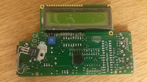
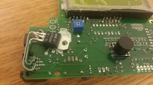
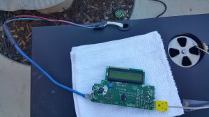
I soldered up my heater meter this weekend. I added a 3.3V voltage regulator to the blower output and connected the Vout to pin 2 on the rj45 jack.

That way if I want to use the blower in the future it remains untouched on its native pin. The MES relay will be attached to ground and my pin 2.
 

Attachments

  • 20180121_151428.jpg
    20180121_151428.jpg
    114.9 KB · Views: 90
  • 20180121_151439.jpg
    20180121_151439.jpg
    106.4 KB · Views: 95
I'm pretty sure Tiros is using the stock mechanical relay with his PID project. He basically built a heat meter from scratch, but only using a 5V micro controller and a cheap wifi board.
He's pretty tight lipped about his schematics and source code, however. I guess that is his prerogative.

Not really, its nothing proprietary.

Here's some details:
The Esp8266 I use is a micro controller with built in Wifi. It runs at 3.3 volts. The board has a linear regulator.
The Microchip part is the 12 bit spi A/D, it is not the controller. There also 2 quad op amps for buffering, along with some resistors and capacitors.

The Esp8266 is fully supported by the Arduino guys. You can even use the Arduino IDE.
I am using the BLYNK platform for IOT. I use a local Raspberry Pi Blynk server for lowest latency, and unlimited app resources (free energy).

I see your post says the transformer is only 250ma. I'm not sure my Gen1 has. Esp uses more than that iirc but I think only in surges, maybe a big cap would help. Maybe I am under powered. I didn't see any power issue on my scope.

As for the relay:
Basically the PID interrupt occurs ever 200msec, and it evaluates every 60 seconds. At the eval point it decides the power level for the next 60 seconds. If its too small, it saves the small bit and adds it to next eval. This way the relay doesn't get pulsed on too short of a time, and still preserves the smaller results.
To Wit:
////RELAY OUTPUT CODE: We are here at pid timer rate
////This code executes at pid timer speed, NOT AT PID COMPUTE SPEED!
//turn the output pin on/off based on pid output
//Limit minimum on/off time, per PID cycle
void outputToRelay(double output, int bNewPidCalc)
{
unsigned long RelayMillis;
static int iMakeUpMillis=0, iOweMillis=0;

if(output<0) output=0;
if(output>PWM_STEPS) output=PWM_STEPS;

RelayMillis=(unsigned long) (output+.5)*(PID_CYCLE_TIME/PWM_STEPS);
//RelayMillis=1000;
//RelayMillis=29000;
//RelayMillis=4500;

if(bNewPidCalc) {
iMakeUpMillis=iOweMillis;
//Serial.print("iOweMillis: ");Serial.print(iOweMillis);Serial.print(" iMakeUp: ");Serial.print(iMakeUpMillis);Serial.println();
}

RelayMillis+=iMakeUpMillis;

//A short turn skips this cycle and adds to next cycle
if(RelayMillis < RELAY_MIN_TIME && RelayMillis) {
iOweMillis=RelayMillis;
RelayMillis=0;
}
//A short turn off subtracts from next cycle
else if(RelayMillis > PID_CYCLE_TIME-RELAY_MIN_TIME && RelayMillis < PID_CYCLE_TIME) {
iOweMillis=RelayMillis-PID_CYCLE_TIME;
RelayMillis=PID_CYCLE_TIME;
}
else {
iOweMillis=0;
}

unsigned long now = millis();
if(now - windowStartTime>=WindowSize) { //time to shift the Relay Window
windowStartTime += WindowSize;
}
if(RelayMillis >= now - windowStartTime) HeatControl(1);
else HeatControl(0);
}

As for the sensor:
In my gen 1, the internal sensor is supplied with 5 volts from the MB regulator. With a suitable terminator, I can read that, but the output will be referenced to the 5 volt supply. Not the best situation for a ratio metric A/D. Better is to use an external probe. I use Thermoworks, it comes with a nice little grate clip too.

Mine is hand wired. If you want to make a board up, I can help you out.
 
  • Like
Reactions: jr_ece
And there you go folks.
The code and logic for managing the relay for an MES in a practical manner :)
 
I soldered up my heater meter this weekend. I added a 3.3V voltage regulator to the blower output and connected the Vout to pin 2 on the rj45 jack.

That way if I want to use the blower in the future it remains untouched on its native pin. The MES relay will be attached to ground and my pin 2.

Sounds awesome!
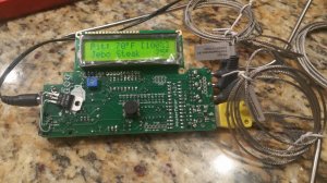
I cheated and bought the whole HM intact from Auber :D
 
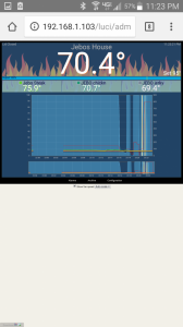
It seems to be working well, the output is 3.3V when trying to raise the pit temp, and 0V when it reaches the correct temperature.

I'll attach it to the smoker for final testing before I internalize the 12V transformer and 3D print a case.
 

Attachments

  • 20180122_232348.jpg
    20180122_232348.jpg
    137.3 KB · Views: 87
  • Screenshot_2018-01-22-23-23-24.png
    Screenshot_2018-01-22-23-23-24.png
    370.8 KB · Views: 84
It seems to be working well, the output is 3.3V when trying to raise the pit temp, and 0V when it reaches the correct temperature.

I'll attach it to the smoker for final testing before I internalize the 12V transformer and 3D print a case.

Looks awesome and exciting! I can't wait to see it hooked up and then all put together :)

Also are you changing out the safety rollout limit switch for a higher threshold one? Just curious :)
 
Looks awesome and exciting! I can't wait to see it hooked up and then all put together :)

Also are you changing out the safety rollout limit switch for a higher threshold one? Just curious :)

No I have no plans to touch the limit switch. If it ain't broke...

As far as I can tell, most PID mods are bypassing the switch entirely. By using the stock wiring and controlling the heating element in the same manner as the stock controller, the innate safety features should remain intact.

Also, it appears that almost all features on the heater meter function with 5v power to the pi... with the exception of the piezo buzzer and the 12V blower output. If I were to rewrite the code to use a digital output pin on the atmel microcontroller instead of the one controlling the blower, this whole thing could potentially run off of the built in 5v in the MES.

The pi zero W seems not as power hungry as it's elder brethren...

That's good to hear.
The pi version in my setup was fine until I hooked up everything to it and then added wifi. It would spike and stave and that would cause a reboot until I got a 3A power supply.

If you hook everything up and then run into the issue you know where to look for a fix :)
 
Pretty stoked right now!

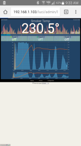
HM is running entirely off of the 5V supplied by the MES. I used your PID settings and set the temp to 230. I got a little freaked out when it initially shot up to 275' and was ready to abort but then it brought itself back down and has been holding steady.

At least with a Pi Zero W, the built-in power supply seems sufficient. I am powereing it through the 5V pin on RJ45 port. Web server is running great.

In other words, HM can run without any additional power supplies or relays on stock MES!

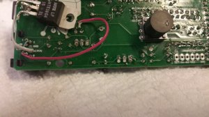
I did do one more modification to the HM. I ran a jumper wire from pin 5 of the atmel microcontroller to an output pin on the RJ45 jack (Red wire in pic). That pin puts out 3.3V when blower is on, and 0V when off. This interfaces directly with the relay built into the MES (red wire in my case). The 3.3V voltage regulator I previously installed is not necessary (I will likely remove it before I install in the case).

The only functionality missing without a 12V power supply is lack of Piezo Buzzer... but that drove my wife crazy anyways. A text message is much more useful as an alarm.
 

Attachments

  • 20180124_083319.jpg
    20180124_083319.jpg
    92.9 KB · Views: 83
  • Screenshot_2018-01-24-09-33-32.png
    Screenshot_2018-01-24-09-33-32.png
    379.2 KB · Views: 80
  • 20180124_080030.jpg
    20180124_080030.jpg
    97.3 KB · Views: 77
Pretty stoked right now!

HM is running entirely off of the 5V supplied by the MES. I used your PID settings and set the temp to 230. I got a little freaked out when it initially shot up to 275' and was ready to abort but then it brought itself back down and has been holding steady.

At least with a Pi Zero W, the built-in power supply seems sufficient. I am powereing it through the 5V pin on RJ45 port. Web server is running great.

In other words, HM can run without any additional power supplies or relays on stock MES!

I did do one more modification to the HM. I ran a jumper wire from pin 5 of the atmel microcontroller to an output pin on the RJ45 jack (Red wire in pic). That pin puts out 3.3V when blower is on, and 0V when off. This interfaces directly with the relay built into the MES (red wire in my case). The 3.3V voltage regulator I previously installed is not necessary (I will likely remove it before I install in the case).

The only functionality missing without a 12V power supply is lack of Piezo Buzzer... but that drove my wife crazy anyways. A text message is much more useful as an alarm.

Man that is exciting and awesome as hell!
I bet that when you have some load in the smoker you don't spike so high.

I don't know how the responsiveness of your unit would much different from my unit but no two things are the same :)
After a little testing you may want to try and tweak the PID values to avoid such a large overshoot if it still persists. Just know that it took me quite a bit of tinkering to find the PID numbers I posted so don't get discouraged if you don't get it right the 1st time (or the 2nd - 50th time lol). I think with some load it won't overshoot as much.

As for the buzzer it is damn near useless in my opinion. The PitDroid phone app and alarm do well for me so I don't have to be within earshot of the smoker when the alarms go off :)

Just be sure the Lid Open Detection settings are set (0% and 30 seconds) to effectively disable that "feature". Lid Open Detection will drive you nuts and surely extend your smoking time if it goes off :)

Keep the posts coming, I can't wait to see more... Maybe even a Stock MES HM setup guide some day :D
 
Yeah, I realize now that there are several parts of the HM board that you don't even need to populate for an MES, but who knows when it will be used for another type of smoker that will require them.

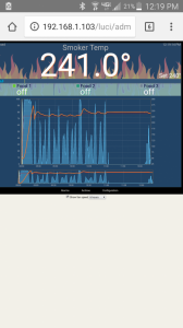
After about an hour I increased the temp up to 240. Overshot again but not as much. I agree with some meat in there it might not be such a big deal.

I don't think I could even come close to your masterful OP... I'll just tag on here if you don't mind.
 

Attachments

  • Screenshot_2018-01-24-12-19-16.png
    Screenshot_2018-01-24-12-19-16.png
    379.4 KB · Views: 65
SmokingMeatForums.com is reader supported and as an Amazon Associate, we may earn commissions from qualifying purchases.

Latest posts

Hot Threads

Clicky