Navigation
Install the app
How to install the app on iOS
Follow along with the video below to see how to install our site as a web app on your home screen.
Note: This feature may not be available in some browsers.
More options
Style variation
-
Some of the links on this forum allow SMF, at no cost to you, to earn a small commission when you click through and make a purchase. Let me know if you have any questions about this.
You are using an out of date browser. It may not display this or other websites correctly.
You should upgrade or use an alternative browser.
You should upgrade or use an alternative browser.
Successful MES brain transplant! Plug and Play replacement controller = Full PID + Cellular contro
- Thread starter tiros
- Start date
SmokingMeatForums.com is reader supported and as an Amazon Associate, we may earn commissions from qualifying purchases.
@tiros
I am not a programmer by any means, but did you look at this: https://github.com/vitotai/BrewPiLess
There are a couple of people at Homebrewtalk who have done a lot of work that may help expand on what you are doing here, especially not needing a RPI.
I am not a programmer by any means, but did you look at this: https://github.com/vitotai/BrewPiLess
There are a couple of people at Homebrewtalk who have done a lot of work that may help expand on what you are doing here, especially not needing a RPI.
@tiros I registered just to say I would buy this in a heartbeat as a kit or complete unit. You could even offer an upgraded model with an LCD/OLED display and a couple buttons so it could be used without a phone and/or wifi. Seems like a lot of people are buying more expensive PID controllers that require more modding. If this were available, it would be a no-brainer purchase for any MES in the know (and an alternative repair option when stock controllers die).
If you've decided for sure not to pursue offering a product, it sure would be nice to see this on GitHub or elsewhere so we can make our own! :)
If you've decided for sure not to pursue offering a product, it sure would be nice to see this on GitHub or elsewhere so we can make our own! :)
My MES40 gen1 temps were allways a good 20 degrees low, oven could not make 275. I was tired of staying tethered to my smoker. I was tired of only having one meat probe. I decided to make a new controller, to replace the old controller completely. It is working and usable right now. I have smoked in excess of 200 lbs of food with it!
Features:
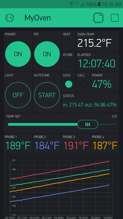
Full PID control with Autotune built in!! Holds within one or two degrees of setpoint.
Full wireless control from anywhwere through my Android device.
8 probe channels, more precise than Heatermeter, thermistor channels are fully buffered.
No modifications to the oven. Remove old controller, replace with this. Easy to switch back to stock.
No separate power supply.
Exports charts and graphs to email.
Uses only about $20 in parts.
Does not require an SSR modification to achieve full PID Control. Just like in the original design, the power is regulated by relay on/off time. My code uses a special anti relay hammering algorithm I developed that insures the relay is not short cycled while still achieving near perfect temp control.
Not real expensive, but a local Rasberry Pi server is recommended somewhere in the home. The Raspi does not have anything to do with controlling the oven. It has no physical connection to the oven. It is used as a wireless bridge from the internet to the new controller. An internet connected always on PC could also be used, but a Pi is cheaper and lower power.
I am using the excellent Thermoworks Pro-Series probes, SKU: #TX-1003X-AP for oven temp and SKU: #TX-1001X-OP for meats. Got them directly from Thermoworks, about $15 each.
In progress right now:
Use two of the 8 channels to buffer and read the built in MES oven and meat probes.
Select any channel as the oven control channel.
Get notification by text or email when a probe reaches set point. (No screenshot yet)
ToDo:
Create some kind of enclosure.
Probably won't generate much smoke when using the chip box. I use an Amazen. I might add some code to allow more temperature swings, (MES mode lol) which translates to more "on" time for the element.
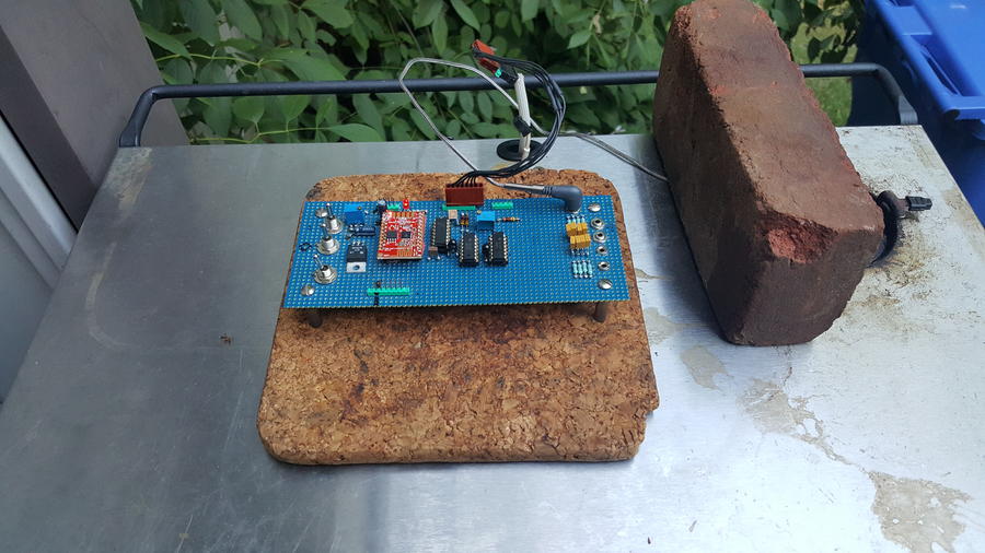
Currently the project exists as a one off bread board. If there seems to be interest, I can lay it out on a pcb. Maybe sell some boards or a kit. I have the MES40 Gen1. From what I have seen, it should be very easy to port the design to another model.
I am trying to monitor the built in MES probes with two of the 8 available channels. I need the Stienharts for those. I have a curve for the meat probe that works ok. That one doesn't work for the oven. If I could remove the oven probe, I could characterize it or replace it. Doesn't seem to be a way to get behind it. It looks like maybe under one of the serial number plates in the back might expose it?
Kurt,
I am not sure I understand maybe I confused things in my explanation. I clarify:
There are two boards in each smoker, the power board, located on the bottom and the control board located on the top. My project replaces completely the top control board. The lower board is not affected in any way. The lower board is the ovens +5 volt power supply and the element control relay. It has some wiring that connects it the top control board. The relay on the power board connects to the control board up top by a blue wire. It also sends up +5 volts by the red wire, and ground on the white one. My control board then can control the relay (by blue wire) to provide heat when it needs to (The PID inside my projects CPU calculates how long to put it on based on temps). There is also a yellow wire for the oven light control coming from down there, so I can control the oven light as well :)
So for my MES-Gen1, I remove the two screws that hold the LED control board on top. Disconnect the 5 pin white plug from it, then connect the plug remaining on the oven to my board. That's it! That's all! Take a look at the photo in my first post, That blue colored board on top of my grill is the ONLY mod. If you look carefully you can see it plugged into the factory wiring harness. You don't cut or add any wires. You can put the old one back any time.
I only mentioned the lower board before to explain how to hot wire the oven to be on all the time for some people who are using PIDs from like Amazon or Ebay. It had nothing to do with my project at all.
Tall:
Thanks. Your build inspired me to try this.
As for the case, I don't know what to do. Currently I flip a rectangular plastic container on top of the blue board, like a tent. :)
I don't want the probe jacks to get wet if it rains. They need to be under some kind of a "roof" in the enclosure I think.
I was also thinking that it would be nice to solder those jacks right to PCB, maybe on the edge, then abut the PCB to case somehow so they can poke through.
I am wide open for any Ideas you have!
I need electronically smart guys oppinions...
My MES40 gen1 temps were allways a good 20 degrees low, oven could not make 275. I was tired of staying tethered to my smoker. I was tired of only having one meat probe. I decided to make a new controller, to replace the old controller completely. It is working and usable right now. I have smoked in excess of 200 lbs of food with it!
Features:
Full PID control with Autotune built in!! Holds within one or two degrees of setpoint.
Full wireless control from anywhwere through my Android device.
8 probe channels, more precise than Heatermeter, thermistor channels are fully buffered.
No modifications to the oven. Remove old controller, replace with this. Easy to switch back to stock.
No separate power supply.
Exports charts and graphs to email.
Uses only about $20 in parts.
Does not require an SSR modification to achieve full PID Control. Just like in the original design, the power is regulated by relay on/off time. My code uses a special anti relay hammering algorithm I developed that insures the relay is not short cycled while still achieving near perfect temp control.
Not real expensive, but a local Rasberry Pi server is recommended somewhere in the home. The Raspi does not have anything to do with controlling the oven. It has no physical connection to the oven. It is used as a wireless bridge from the internet to the new controller. An internet connected always on PC could also be used, but a Pi is cheaper and lower power.
I am using the excellent Thermoworks Pro-Series probes, SKU: #TX-1003X-AP for oven temp and SKU: #TX-1001X-OP for meats. Got them directly from Thermoworks, about $15 each.
In progress right now:
Use two of the 8 channels to buffer and read the built in MES oven and meat probes.
Select any channel as the oven control channel.
Get notification by text or email when a probe reaches set point. (No screenshot yet)
ToDo:
Create some kind of enclosure.
Probably won't generate much smoke when using the chip box. I use an Amazen. I might add some code to allow more temperature swings, (MES mode lol) which translates to more "on" time for the element.
Currently the project exists as a one off bread board. If there seems to be interest, I can lay it out on a pcb. Maybe sell some boards or a kit. I have the MES40 Gen1. From what I have seen, it should be very easy to port the design to another model.
I am trying to monitor the built in MES probes with two of the 8 available channels. I need the Stienharts for those. I have a curve for the meat probe that works ok. That one doesn't work for the oven. If I could remove the oven probe, I could characterize it or replace it. Doesn't seem to be a way to get behind it. It looks like maybe under one of the serial number plates in the back might expose it?
I got this idea from ya'll so here goes. I bought an Ink Bird
I don't know. I can use a multi meter to figure stuff out but not code or build PCBs. In the description of the controller and sensor the sensor may have a different range than -50~210. The display may be limited to -50~210 so even if the pit boss sensor is compatible the controller may not go higher than 210.I need electronically smart guys oppinions...
I got this idea from ya'll so here goes. I bought an Ink Bird View attachment 448778ITC-1000F to control the heat in my electric Pt Boss smoker. Then I got online to get ideas for parts and came up with a fully functioning thermo-regulator that looks pretty cool. Problem is I didn't review the details enough to know that the Temperture Set Value -50~210 °F and of course the avg temp in the smoker runs higher than that. My question is can I just switch the temperature sensor out with the one in the smoker to change the Temp Set Value higher?
drewb0y
Fire Starter
- Jul 5, 2020
- 36
- 13
I second this. If you could post a schematic and the code at least that would be awesome.@tiros I registered just to say I would buy this in a heartbeat as a kit or complete unit. You could even offer an upgraded model with an LCD/OLED display and a couple buttons so it could be used without a phone and/or wifi. Seems like a lot of people are buying more expensive PID controllers that require more modding. If this were available, it would be a no-brainer purchase for any MES in the know (and an alternative repair option when stock controllers die).
If you've decided for sure not to pursue offering a product, it sure would be nice to see this on GitHub or elsewhere so we can make our own! :)
TheEyeTGuy
Newbie
- Jul 13, 2020
- 15
- 4
Agreed. Schematic and code would be great!
drewb0y
Fire Starter
- Jul 5, 2020
- 36
- 13
It looks like the original poster has not been around in a while. Last post was end of January.Agreed. Schematic and code would be great!
TheEyeTGuy
Newbie
- Jul 13, 2020
- 15
- 4
That's an absolute shame.It looks like the original poster has not been around in a while. Last post was end of January.
I need electronically smart guys oppinions...
I got this idea from ya'll so here goes. I bought an Ink Bird View attachment 448778ITC-1000F to control the heat in my electric Pt Boss smoker. Then I got online to get ideas for parts and came up with a fully functioning thermo-regulator that looks pretty cool. Problem is I didn't review the details enough to know that the Temperture Set Value -50~210 °F and of course the avg temp in the smoker runs higher than that. My question is can I just switch the temperature sensor out with the one in the smoker to change the Temp Set Value higher?
Hi there and welcome!
I think the unit may not be able to display or handle signal to indicate above 210F.
It sucks but for about $40-50 I bet you could buy a different PID and an SSR (if u are not using one) and just replace the PID you have and u should be ready to rock and roll. You can always use this unit for Sous Vide cooking or beer brewing if u do either of those hobbies.
I would also buy a different probe that was 6ft long and I'm partial to the ones with an aligator clip so u can move it around easily for more accurate temp readings not these wall mount types.
I hope this info helps :)
rick123
Newbie
@tiros I know this is an old thread but I'm working on a project very similar to yours based on an esp8266. I may have wasted some effort though after reading through this thread. 
I am using 3 MAX31850K thermocouple amplifiers to read 3 probes currently. I went this route both for accuracy and because I could not find anything solid on how to read something like a Thermoworks thermistor probe like you seam to be using. Could you explain how you are reading the Thermoworks probes accurately and how you calibrated them? Essentially, it comes down to cost. The thermocouple route was easy and accurate but is much more expensive.
I also built my own relay control board using an OMRON electromechanical relay driven by 5v signal. I had to use an NPN transistor to control the 5v signal of course from 3.3v . I was originally going to do a SSR like others have but was concerned about heat build up as I have seen some pictures of these things melted. I was happy to see the existing relay on the MES is driven with 3.3v signal and may now simply mount my PCB inside the existing front panel of my Gen 2.5 MES. It looks like I even have room for the MAX31850K boards and sockets the the K Type probes. Which leads to my second question. Since you did your MOD, have you had any issues with the original MES relay?
I am using 3 MAX31850K thermocouple amplifiers to read 3 probes currently. I went this route both for accuracy and because I could not find anything solid on how to read something like a Thermoworks thermistor probe like you seam to be using. Could you explain how you are reading the Thermoworks probes accurately and how you calibrated them? Essentially, it comes down to cost. The thermocouple route was easy and accurate but is much more expensive.
I also built my own relay control board using an OMRON electromechanical relay driven by 5v signal. I had to use an NPN transistor to control the 5v signal of course from 3.3v . I was originally going to do a SSR like others have but was concerned about heat build up as I have seen some pictures of these things melted
. I was happy to see the existing relay on the MES is driven with 3.3v signal and may now simply mount my PCB inside the existing front panel of my Gen 2.5 MES. It looks like I even have room for the MAX31850K boards and sockets the the K Type probes. Which leads to my second question. Since you did your MOD, have you had any issues with the original MES relay?The relay on the power board connects to the control board up top by a blue wire. It also sends up +5 volts by the red wire, and ground on the white one. My control board then can control the relay (by blue wire) to provide heat when it needs to (The PID inside my projects CPU calculates how long to put it on based on temps). There is also a yellow wire for the oven light control coming from down there, so I can control the oven light as well :)
Do you know the purpose of the black wire? I uncovered the power supply board under my smoker and found the black wire is labeled STOVE-T.
Is that STOVE Thermostat or Temperature??
It is also routed to the 2 pin header that's next to the 5 pin along with +5V.
I wanted to follow up with an answer for anyone following this thread. The STOVE-T has 5V applied by the power board (shown above) that then runs through the thermostat and finally routed up to the control panel where it monitors this signal for open/close. From a quick test, the control panel beeps and kicks off the heating element relay when 5V is present indicating the thermostat closed due to an overheating condition. You can see the 2 pin header that runs out to the thermostat. By looking at the back of the power board one can see the STOVE-T and +5V signals (shown in pic above) are simply routed from/to the 5 pin header that routes to the control panel.
Hope this helps someone.
Hope this helps someone.
Great thread. Thanks @tiros , @jr_ece, and others.
I've been trying to find the pinouts in order to use a 4-pin controller on a 5(+2) pin smoker. I figured out pins 1 (+5V), 3 (gnd), and 4 (element relay), and they are the same on both 4 and 5-pin connectors. When I connect pin 2, I get ERR1, so that must be different on the 4-pin system.
Putting +5V on Pin 5 turns on the light (via a relay).
The controller also gets a temperature reading with only Pin 1 and 3 connected, which is a little confusing. I wonder if someone can explain? The sensor seems to be malfunctioning and I'd like to wire in something else.
I might just build my own - I've got a simple Arduino controller running now using a thermocouple + MAX6675 board. The tricky part is wiring up a display + an input mechanism so I can check the temperature and change setpoint.
MM2021,
From my research I believe the 5 position connector numbering is reversed from how you've referenced them. I know it really doesn't matter for our discussion, but just wanted to be accurate to the original design in case others catch up with our dialog.
If I'm right...
Controller connectors
CN2
5 -- +5V (red wire)
4 -- STOVE-T (back wall temp sensor?); causes err if controller gets +5V on this input, probably due to this being max temp?
3 -- GND
2 -- HEAT (+5V from controller closes relay on power board, turns on 120VAC element)
1 -- LIGHT (+5V from controller closes relay on power board, turns on 120VAC light)
CN3
2 -- +5V (out to meat probe)
1 -- AD (meat probe return input to micro controller)
If the 4 pin controller you are using has a LIGHT control button then the only remaining (missing) signal seems to be STOVE-T. In this case there is nothing to do with this signal in relation to the controller, but you could still monitor with your own circuit (buzzer, LED, etc).
From my research I believe the 5 position connector numbering is reversed from how you've referenced them. I know it really doesn't matter for our discussion, but just wanted to be accurate to the original design in case others catch up with our dialog.
If I'm right...
Controller connectors
CN2
5 -- +5V (red wire)
4 -- STOVE-T (back wall temp sensor?); causes err if controller gets +5V on this input, probably due to this being max temp?
3 -- GND
2 -- HEAT (+5V from controller closes relay on power board, turns on 120VAC element)
1 -- LIGHT (+5V from controller closes relay on power board, turns on 120VAC light)
CN3
2 -- +5V (out to meat probe)
1 -- AD (meat probe return input to micro controller)
Last edited:
I'm assuming the relay and voltage regulator or what ever your using at the lower PCB is attached as one piece being the PCB. According to MB the lower PCB in the Gen 1 40 is not serviceable so when it fails the smoker is a goner so they riveted the access plate on. It's like MB built the smoker around the Gen 1 PCB. The Gen 2 and 2.5 I believe have all end user accessible plates to the PCB's that are replaceable so the plates have screws. So when the Gen 1 PCB fails you may be able to hack that board whereby the Gen 2 or 2.5 owners can just get a new PCB from MB. That's why I was wondering if your controller is best used on Gen 2 or 2.5. Us novices that can solder and terminate wires but can't hack circuit boards when they fail would be stuck with your fantastic top controller on the Gen 1 when the PCB fails. So I was wondering for the long run with the Gen 1 do TallBM's PCB bypass with a plug and play PID and do your top controller plug and play on the Gen 2 and 2.5. I hope this helps. TallBM may chime in if I'm way off. He has crawled around inside a Gen 1 and 2 as well.
-Kurt
Kurt,
You are correct that the Gen 1 Power Board in the bottom is really meant to be permanent with rivets holding the cover in place. My Power Board failed shorted and pushed the smoker to over 300 deg F before I realized it. I drilled the rivets, cut through the white rubber type coating, and removed it. Sadly, the 5 pin (to controller on top) and 2 pin (thermostat) connectors have their pins soldered to the PCB. I desoldered them, troubleshot the board and replaced a couple of components to return it to service. I also purchased mating Molex connectors and pins and added headers and connector plugs so my Gen 1 is now serviceable. Upon working through all of this I believe that I can now purchase one of the newer serviceable Power Boards if the current board fails beyond repair (e.g., transformer). Point is, with a little work and the addition of 2 plug connectors the Gen 1 can be made serviceable. The hardest part is removing the white rubbery coating without damaging the PCB for the component repairs. note, I used a paint can opener to get under the edge of the PCB to pull it out of the cavity. As for the cover, I was originally thinking I would use screws or small fasteners to reinstall. I ended up using "baling wire" to loop through several of the mounting holes and then crossing over the middle back to the beginning of the wire. This allowed for using Lineman's pliers to put a good twist on the wire ends and cinch down the cover.
Ahh! now I understand the concern.
I was not aware the lower pcb was not serviceable. I just checked mine, and there are rivets not screws :(
However I do have a drill :) The question is this: Can that lower PCB be removed at all?
If so, it can be repaired. It is a very simple circuit. Another option might be to use the board used to repair the other style. Another option, duplicate that board.
Tall:
In this photo:
http://www.smokingmeatforums.com/t/63863/masterbuilt-not-working-properly/160#post_1676242
There seems to be two lower boards. The yellow has screws, the white does not. What are these from?
I'm sure that yellow board can replace the white one. If not directly, with some small modification,
My control board needs only 3 things from any host to operate, +5, Gnd, and a control line for the element. The temperature sensor is supplied by a probe. So yes the board could drive a relay box, plugged in to a rewired oven. It could drive a kitchen oven. It could drive a toaster oven. It could drive a sous vide heating element. It drive run any kind of heater if there is a way to control the power element.
I built this for Gen1 only because that's what I have. The project hardware would be basically the same for any heating device I want to control. Some small tweaks to the code would allow it to work on really any kind of heater. I suspect MB uses the same config for all their units and I would likely be able to find the 3 connection points I need for any model they make without any change to my hardware. These 3 points are easy to find. I could probably find them by looking at a photo of the PCB solder side, if anyone cares to post a pic.
Very doable. See my previous post where I mention Gen 1 Power Board removal.
@jr_ece thanks for clarifying the order.
The 4 pin controller has no LIGHT button.
I'm still trying to get my head around the STOVE-T signal. When you say thermostat above, do you mean the (high temp cut-off) thermal switch? And by probe, do you mean the temp sensor on the back wall, or the meat probe (my smoker has both). I read somewhere that the power to the element was wired through that switch, but maybe it's different on this model?
It's still not clear to me how controller gets the temperature reading from the temp probe on the back wall.
I made my own simple controller with an Arduino and a thermocouple/max6675 board. No PID control, I need a bit of fluctuation to get smoke.
@jr_ece thanks for clarifying the order.
The 4 pin controller has no LIGHT button.
I'm still trying to get my head around the STOVE-T signal. When you say thermostat above, do you mean the (high temp cut-off) thermal switch? And by probe, do you mean the temp sensor on the back wall, or the meat probe (my smoker has both). I read somewhere that the power to the element was wired through that switch, but maybe it's different on this model?
It's still not clear to me how controller gets the temperature reading from the temp probe on the back wall.
I made my own simple controller with an Arduino and a thermocouple/max6675 board. No PID control, I need a bit of fluctuation to get smoke.
MM2021,
Ah, so the light is the missing line.
Yes, STOVE-T is the label on the Power Board (see one of my post above for pic)
My unit also has the temperature sensor on the back wall and meat probe hanging inside. I've done nothing with the meat probe to this point since I have a Maverick 4 probe unit to measure temps. It's a good question. There are few options here it seems
Last edited:

SmokingMeatForums.com is reader supported and as an Amazon Associate, we may earn commissions from qualifying purchases.
Similar threads
- Replies
- 2
- Views
- 235
- Replies
- 0
- Views
- 550
- Replies
- 0
- Views
- 6K
SmokingMeatForums.com is reader supported and as an Amazon Associate, we may earn commissions from qualifying purchases.

SmokingMeatForums.com is a community of barbecue and outdoor cooking enthusiasts dedicated to smoking meat.
© 2004-2026 SmokingMeatForums.com