I'd just make sure anyone tests this to be true. On my MES the roll-off (safety switch) was not connected to the control board. I did not have two hot insulated black wires from my control board.
Yeah it is always best to verify. The internet is full of inaccurate and bad data for sure!

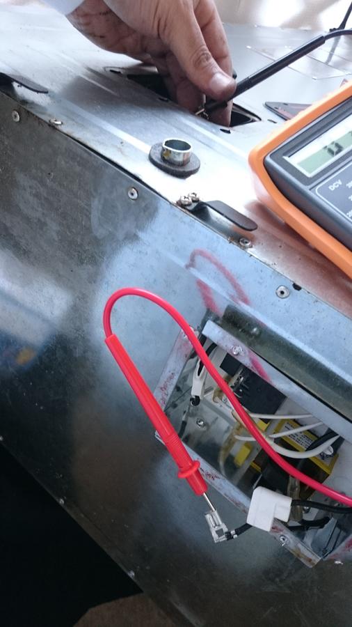
I don't have all the pics but I was able to dig up this one where I did continuity checks to verify the wiring.
That image was from one of my mod posts here... I have heavily modded my MES lol
https://www.smokingmeatforums.com/threads/mes-mod-madness-teaser-pics.261790/
Unless
Masterbuilt has changed things recently, the big braided wires (not little thin ones) should have 1 wire going to the heating element (neutral) and the other wire going to the safety rollout limit switch (hot). The saftey rollout limit switch then has the outgoing wire going to the heating element.
The best approach for checking these wires is to unhook the smooth wires from the circuit board and unhook the big braided wires from the circuit board.
Next unhook the braided wires from the heating element.
If you have an MES model with the rollout limit switch panel then remove the panel. If not then remove the back of the MES so that you can get to the rollout limit switch.
It is absolutely mandatory that all of the unhooking I mention actually be done or else someone will get a false continuity reading since the heating element hooks together both braided wires making it impossible to tell one vs the other.
With the multimiter's continuity setting, check from the plug prongs to the smooth wire ends to find out which prong is hot and which prong is neutral, and confirm with the wire color coding (white = neutral, black = hot). This lets you know the multimeter is working properly and for no real good reason, lets you know which prong of the plug is the hot prong lol.
Next check the braided wire ends. One end of the wire at the circuit board, the other end of the wire at the heating element. You can find which braided wire ends belong to one another.
Now here is where you go a step further to find out which braided wire goes to the safety rollout limit switch.
Touch a multimeter test prong on one of the connector ends of the safety rollout limit switch (DO NOT UNHOOK THE WIRE FROM THE SWITCH).
Touch the OTHER test prong to the end of one of the braided wires at the circuit board. When you find the one that beeps at the circuit board side label that braided wire at the circuit board side.
Now keep one test prong on the safety rollout limit switch prong but place the other test prong on a braided wire at the heating element and find the one that beeps. Label that braided wire.
Now DOUBLE CHECK that the labeled braided wire at the circuit board and the labeled braided wire at the heating element cause the multimeter to beep on the continuity setting. They should.
You now know that the labeled braided wire at the circuit board travels up to the rollout limit switch. You also know that the braided wire that comes out of the other end of the rollout limit switch travels to heating element.
You can now double check the non labeled braided wires at the heating element and circuit board to know they are the same wire, they beep :)
How do I know all of this and know there are no other connections in between?
Well I bought a used MES40 on craigslist for $40, pulled off the back, and pulled up every single wire I could find and checked them for continuity so I could perform a rewire job and add a PID controller hahahha.
At that time there wasn't much good info in any single place to understand how to do this job for the MES. There was info on the Bradley but not the MES.
I still encourage people to verify with a multimeter because you never know until you absolutely know. As long as
Masterbuilt doesn't drastically change things a simple continuity check of the braided wires unhooked from the circuit board and the heating element should let folks know that those wires are a continuous circuit between the circuit board and the heating element :)
I believe the light blub is controlled strictly through the MES controller and circuit board via the other wiring. I'm positive it not on the same wiring circuit as the braided wires we are currently speaking about because those wires don' go anywhere else.
I have however never pulled up the wiring for the light bulb/socket because it goes in through the side of the MES and I didn't explore wiring beyond the back (and back top for controller).
I hope this info helps :)