I need help wiring in my new electric forced air furnace...

  • Some of the links on this forum allow SMF, at no cost to you, to earn a small commission when you click through and make a purchase. Let me know if you have any questions about this.
SMF is reader-supported. When you buy through links on our site, we may earn an affiliate commission.

daveomak

SMF Hall of Fame Pitmaster
Original poster
OTBS Member
★ Lifetime Premier ★
Nov 12, 2010
27,123
4,978
Omak,Washington,U.S.A.
I have a furnace in the attic.. I'm installing this furnace inside my home to eliminate heat loss due to duct work etc..
When my attic is 10 F, the 150+ ft. of duct work doesn't cut it... OH !! FWIW, my home is 75 years old..

What I want it to do...
I need heat.....
I need "summer fan" switch so I can have the fan run continuously....
and I need to hook up the thermostat.....
and I want to know how to adjust the fan speed...

I'm an IDIOT when it comes to electrical diagrams...
The furnace is a Goodman HKR-10..... Rev C.... Air Handler 9.5 KW / 240v... 34,120 BTU 10KW

I think this unit does not have a variable speed fan.... Can you tell me how I can make it variable speed ??

I plan on a simple bi-metal thermostat... maybe... What do you think ..

OK.. What have I forgot....


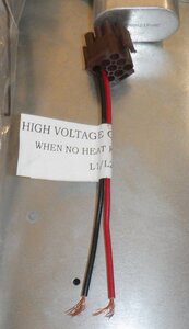
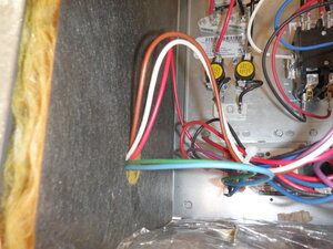
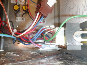
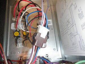
DSCF0049.JPG .. DSCF0050.JPG .. DSCF0051.JPG .. DSCF0052.JPG
 
Last edited:
"Furnace" made me think of gas burners, but this appears to be all-electric heat source based on HKR-10 product literature. This will be costly heat...if it's running 20% of the time 6 months of the year, that's an average power draw of 10% of 10kW or 8760 kW-hr per year, not counting the blower motor (probably an MBR-0800?) power. At about 20 cents per kWh, that's almost $2000 every year just to pay for the electricity for this.

This is a lot of electricity....probably a 60A circuit at normal household split-phase 240V. If you don't already have this installed, you'll probably need a pretty costly upgrade to your electrical feed and main panel.

Per unit of heating energy, gas is about half the price of electricity (especially since fracking became so financially attractive) so upgrading your existing furnace to give you an extra 34000 BTU/hr would soon pay for itself in just a few years. You may want to spend a little money wrapping better insulation around the existing ductwork in your attic and you may find your existing furnace (without this 10kW electrical heater) gets you plenty warm and with no added energy costs.

If the blower really is an MBR-0800 it's probably already wired to run at max speed to keep the 10kW filaments from overheating and burning the house down so a single jumper would allow you to run the blower non-stop in the summer (with a $20 thermostat set to min so filaments never fire up) but do you maybe want to re-think the cost/benefit analysis on this first?
 
Bill, I have run the cost benefit analysis...
I use 6 tons of pellets per winter and $200/ton = $1200/7 months per winter or ~$171per month for heat only....
1 ton of pellets @8,000 BTU per pound X 2,000# X 6 tons = 95M BTU in heat... = ~28,000 kW hours
28,000 kW hours X $0.07 = $1,960 for heat....
My pellet stove works "overtime" as is runs continuous so it's wasting probably 20% of it's heat and it's probably 85% efficient so there's another 15% wasted....
So, theoretically, let's "assume" it's total efficiency at 65%...
95M BTU X 0.65 = 62M BTU to actually heat the home at a comfortable temp...
So that $1,960 electric bill now becomes $1274 for the 7 month period...
PLUS.... it gives me the opportunity to leave my home and not have it freeze...
Currently I only have a pellet stove for heat... When the temperature doesn't get above freezing for ~4 months, that's a problem....
In post 1 I noted I was replacing a furnace in the attic... It is also electric and it's HUGE... And it wastes a lot of heat being in the attic... So, I have the electrical already in place...
My pellet stove is rated at 30,000 BTU's... The NEW electric furnace is 35,000 BTU's... Since electricity is 100% efficient the costs are about equal... I'm gonna use the electric as a "base" heat and supplement it with the pellet heat... I'm thinking set the thermostat at ~65ish and burn a few pellets to raise the temp up a bit...
There is another plus to this... having an AIR FILTER to knock down the dust... I have 4" thick pleated filters with carbon secondary to clean the air... they are waiting for the install....
I just wish I could understand the electrical schematic.....
 
Last edited:
Looks like you have a 2-speed motor. (Hi/low). You will probably need to install a relay to switch the speeds.

Where and how do I do that ???
--------------
I need heat.....
Which wires do I connect the incoming 220V to ??

I need "summer fan" switch so I can have the fan run continuously....
Which wires do I connect to to have a summer fan ??

and I need to hook up the thermostat.....
Which wires are the thermostat ??

and I want to know how to adjust the fan speed...
How do I hook up the relay, and what relay should I get ??
 
I suggest you go visit your local HVAC tech guy and give him all the specs of the furnace. He should be able to help you figure it out. Plus he will have the type of thermostat and relays you need.
 
  • Like
Reactions: JC in GB
7 cents per kw-hr...do you live in Finland? I want the Tesla dealership in your town!

The pictures aren't consistent with the schematics you show. There's a lot of variation in products like this. E.g. this $73 HKR-10 has a different filament layout than this $73 HKR-10. Note the Amazon is closest to what you have (just a single mounting plate) but it clearly has a connection for the beefy 50A fused 240V input connections. Yours doesn't have that...your photos don't anywhere show wiring consistent with 10kW so it's hard to tell you where to connect power. I see holes (above the white strip with all the black arrows) but the big terminal block is missing. Is that lying around somewhere?

The schematic we really need is on the right side of your picture DSCF0052.JPG but it doesn't agree with what you attached. The page 8 wiring diagram would imply your blower is the 10kW model MBR0800. But note that has 4 wires leading to the motor--red,green,white,blue. But from your picture (left side of DSCF0050.JPG) you have 5 wires (note the brown wire) which is for over 10kW models. That alone isn't a big deal but the 5-wire motors have a capacitor start circuit EXTERNAL to the motor. I note your dscf0049-jpg picture appears to show a capacitor going off the picture. It's critical that's connected between the blue and brown wires or you'll burn up your motor. But again I don't trust your posted wiring diagrams so take even that with a grain of salt.

Perhaps the other Dave can explain, but I see nothing to indicate you have anything other than a single speed motor. This thermostat probably will work (note the green wire allows you to run the fan independent of the heat) but we'll need the real schematic to know how to hook it up.
 
OK... Here's more information... Sorry I missed this stuff earlier...

Schematic inside the furnace..
DSCF0072 (2).JPG


Fan and capacitor...
DSCF0064.JPG


Wiring going inside to the controls...
DSCF0065.JPG


Where the wiring comes through the bulkhead....
DSCF0066.JPG


What I think is "POWER IN" terminal block...
DSCF0067.JPG


Ground lug....
DSCF0076.JPG


Heating element terminals....
DSCF0068 (2).JPG


Element sticker... 9.5KW and part #..
DSCF0069.JPG


Heating element...
DSCF0070.JPG

DSCF0068.JPG


OK... I think I may be getting close to figuring this stuff out....

I'm thinking I need a 50 or 60 AMP FEED THRU circuit breaker at the furnace... I have a 60 amp in the panel.... Is that correct ??? which one ???
Connect the "colored" (black) wires to those "Power In" incoming terminals...
Connect the ground wire to the ground lug...
Do not connect the common wire anywhere... Dead end it.... Is that correct ??

Lets forget all the incorrect stuff I put up...
So, which wires to get the thermostat to work ???
Which wires to run the "summer fan" using a single pole/single throw toggle switch or light switch ??
What else do I need ???
 
Last edited:
YES !!! 7 cents per KW hour.... When I moved here it was 3.5 cents per KW hour...
 
According to the schematic, you have an option for a three speed motor. Is that the model you have?

If I knew a bit more about the blower motor specs, I could suggest a motor speed controller.

JC :emoji_cat:
 
I don't think so... But I was thinking I could add a SCR motor speed control to it... but not sure....
 
Been a long time since I worked on them .
Blowers motors normally have 2 speeds , one for cooling one for heating . Cold air doesn't rise , so needs a higher fan speed .

Your drawing shows wiring changes for 3 speeds ( on some units ) length of run , temp of air to be moved needs different speeds .

On the right side of the drawing , the heavy dashed lines are line voltage in , that are provided in the field .

You have low voltage , 24 volts that controls the make up of the contactor , thru the thermostat .
So 24 volts from the unit up to the therm , then back down to , heat , fan , or cooling if you have it .
That's the section that says " see notes 2 and 6 " right side of the drawing .
Says TR ( transformer ) read the notes in that area .
Shows colors of the wire connections .
 
I don't think so... But I was thinking I could add a SCR motor speed control to it... but not sure....

Not all motors can be controlled using an SCR controller. With synchronous AC motors, speed is dependent on line frequency. You must use a device known as a cyclotron to control that type of motor. If you could get a pic of the motor nameplate I could likely figure out what speed control would work for you.

JC :emoji_cat:
 
Thank you, The motor is a witch to remove,, I have to pull the fan and housing from the unit...
The furnace model is... MBR0800aa-1 , hkr-10 Goodman 34,120 BTU .. /The motor is inside the fan housing...
I'm thinking I will live with the blower speed...
 
  • Like
Reactions: JC in GB
I looked up the technical specs on your cooler unit. The bad news is that your unit uses a split phase motor that is not easily subjected to speed control.

To do what you are asking, you would need to remove that motor and replace it with a 3 phase motor then run it using a variable frequency drive.

It sounds like a major pain in the butt to do all that. It would give you precise control though.

JC :emoji_cat:
 
  • Like
Reactions: daveomak
Thanks for the added pictures, incl the motor start capacitor location. I'd still appreciate seeing what the notes say (chopped off at bottom) on the internal schematic. I doubt you have 3phase power at a residence so be happy this is all designed around split phase 240VAC.
If you wire this to a 50A breaker, you'll need to wire at least 6AWG (#6) to this, use #4 if you're coming from a 60A breaker (or fuses). I agree the terminal block you provided extra pics for is meant to be the input...but please verify a .20 drill (13/64 or #6) will fit in those terminals...I'm still concerned that this is somewhat of an orphan unit. E.g. putting the ground stud kitty-corner from the attachment is "legal" but weird.
Nice catch by zwiller on the NEC 424...you need a switch (disconnect means) in eyesight of this so I assume you'll need to get one...note it needs to be 2-pole for both of the split phase 240. I note the Goodman product lit on line all shows that included...but apparently not for you.
That terminal block is part of the main contactor that the thermostat will turn on and off (at 24V levels). The two red and 2 black wires going to the filament connections look wimpy to me. Verify they're at least #12. Normally that's only good for 20A each (40A when paired) but for in-chassis wiring (lots of air cooling) that's OK.
Note the contactor is not on the schematic I requested. Are there any markings on it we can get some info? There appears to be two relay connections...maybe one normally open and one normally closed? We'll want the NO one. For the CT31 thermostat I linked to, the W terminal will go there. The terminal marked R will go to one of 3 unused spigots under the main power in terminals. The Y won't be used...there's no cooling in this system. The G terminal will go to the fan control, but before I commit to that...I'm confused by what appears to be 4 wires going to the blower area through a plain metal hole (what you called the bulkhead) in your latest picture dscf0066-jpg and what I thought was the same thing showing 5 wires going through a thick piece of thermal insulation in dscf0050-jpg.
 
the other reason I think we need details on the heater contactor is to ensure the relay won't draw more current than your chosen thermostat can handle.
 
SmokingMeatForums.com is reader supported and as an Amazon Associate, we may earn commissions from qualifying purchases.

Hot Threads

Clicky