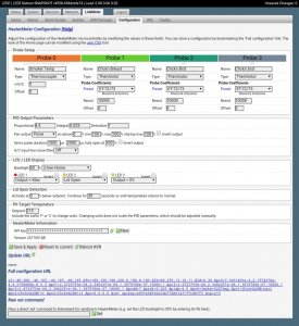
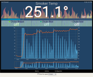
Could you share some details with me about how you went about tuning your PID? My overshoots are crazy high!
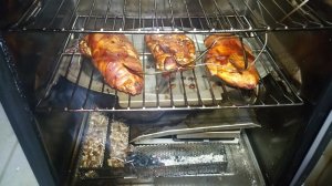
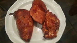
(BUT doesn't that chicken look great?)
Warning: Long post of with lots of boring info lol :D
Well I started from scratch knowing nothing about PID tunning.
I tried to use the types of tunings I could find when it came to the HM and the blower fan BUT it was not apples to apples since the blower fan stokes a heat source and the electric smoker heats up an element. The response time is drastically different.
Then I tried to incorporate some info I found from PID tuning with HVAC systems and again not apples to apples.
The next iteration was to try and and go with really high numbers (in regards to PID) to try and get things in tune since I figured the numbers would course correct more quickly but things were too erratic at various set points, so another approach was needed.
I then tried to use the tunings from the Auber PID from the first MES rewire job that I gave to my mother as a gift. I gleaned more info but again not apples to apples because the algorithms were not the same between the Auber and the HM, so back to the drawing board.
At this point I just went and read up on a bunch of PID tuning in general rather than specific systems (blower + charcoal, hvac, SV, etc.). Armed with my trial and error knowledge, I came to realize that I would have to just start with plain jane PID tuning tactics and start at a base low numbers for tuning and work up to find the right combo.
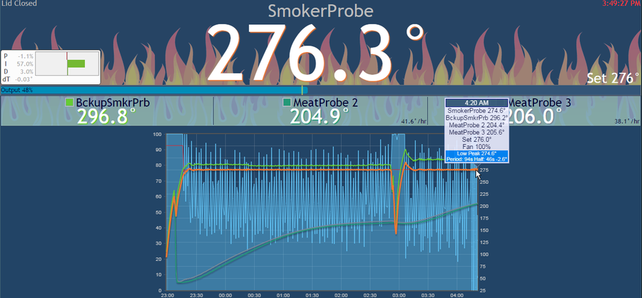
I started with a base low number for P and then gathered my info on it's behavior.
Then on to tuning I and gathering the behavior info.
Finally moving to tuning D and gathering the behavior info.
I went through a number of iterations of this to see what was working along the way an the result of a set of values for the entire PID tuning.
After doing it enough times and gathering the info I found the magic set of values that worked for the HM and it's PID algorithm.
In the end I found that the documentation for the standard HM PID tuning was of no real use because it was all centered around a blower fan and the responsiveness being way faster than an electrical element based system.
I found that it was educational but not very helpful to try and utilize tuning info and values from other systems like HVAC, SV, or the Auber units because their systems had way different performance response times AND each one likely had a different PID algorithm. This meant I was never apples to apples and was always apples to elephants :)
I found that the only thing that worked for me was to do basic principles of PID tuning practice in conjunction with the knowledge I gained from the HM documentation on how the HM PID control behaved in general and the fact that I had a slow responding system compared to most systems out there that are documented or have tuning info available.
With all of that info I was able to try and try again with the most generic of PID tuning practices while understanding my system more with each attempt until I dialed it in :)
Steps that Should Lead to Better Performance
I THINK you have mentioned that you have a different algorithm for your HM so my tuning values may not be spot on.
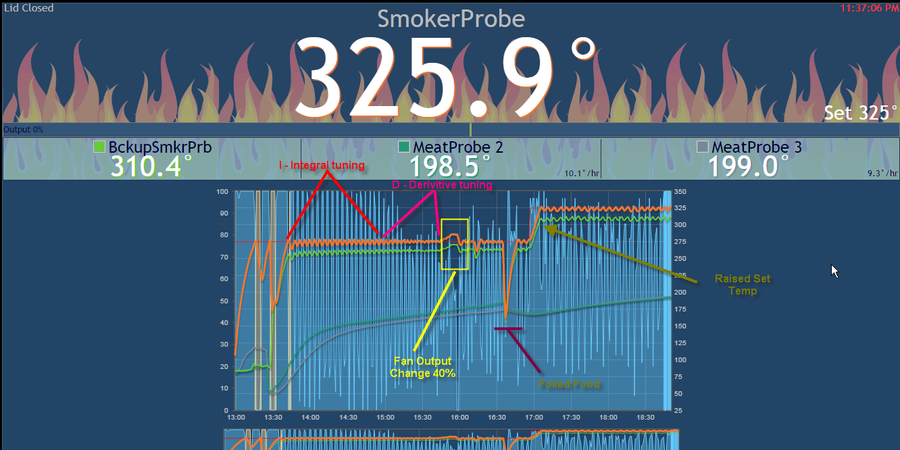
Try to reduce the P value to 3 and see how things respond. Remember that all of the I and D behaviors are going to be calculated off of the P value so only change it and see how things behave. Reducing P in general should reduce overshoot but you also don't want it to fail to hit the set temp.
[EDIT: Removed erroneous portion of the statement.]
From there I would leave the "I" tuning alone.
I would bump D up to like 120 - 140 to see if it can get a minor decrease in overshoot. The idea would be that it would maybe slow the initial ramp up to set temp a little so that it can't overshoot so badly.
Again start with only P and see how things respond.
After a number of P reduction trials, go with the best performing P and then increase D and perform trials there to see if you can help the overshoot.
I think you will get there it just takes some effort. Let me know if any of this info makes sense/helps and ask away if you have any questions. Best of luck! :)
OH, and the chicken does look amazing! Chicken was my go-to with all of this trial and error dialing because it is the cheapest. Man did I get a ton of chicken smoking in and a great appreciation for smoked chicken hahaha! You are on your way to consistently amazing smoked food my friend :D