Successful MES brain transplant! Plug and Play replacement controller = Full PID + Cellular contro

  • Some of the links on this forum allow SMF, at no cost to you, to earn a small commission when you click through and make a purchase. Let me know if you have any questions about this.
SMF is reader-supported. When you buy through links on our site, we may earn an affiliate commission.

tiros

Newbie
Original poster
Jun 5, 2017
24
25

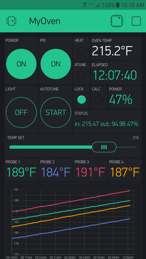
My MES40 gen1 temps were allways a good 20 degrees low, oven could not make 275. I was tired of staying tethered to my smoker. I was tired of only having one meat probe. I decided to make a new controller, to replace the old controller completely. It is working and usable right now. I have smoked in excess of 200 lbs of food with it!

Features:
Full PID control with Autotune built in!! Holds within one or two degrees of setpoint.
Full wireless control from anywhwere through my Android device.
8 probe channels, more precise than Heatermeter, thermistor channels are fully buffered.
No modifications to the oven. Remove old controller, replace with this. Easy to switch back to stock.
No separate power supply. 
Exports charts and graphs to email.
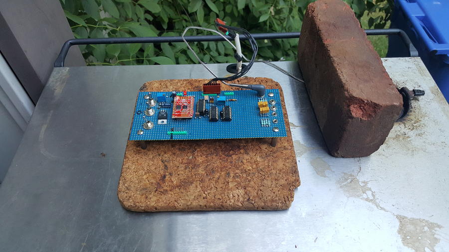
Uses only about $20 in parts.

Does not require an SSR modification to achieve full PID Control. Just like in the original design, the power is regulated by relay on/off time. My code uses a special anti relay hammering algorithm I developed that insures the relay is not short cycled while still achieving near perfect temp control.

Not real expensive, but a local Rasberry Pi server is recommended somewhere in the home. The Raspi does not have anything to do with controlling the oven. It has no physical connection to the oven. It is used as a wireless bridge from the internet to the new controller.  An internet connected always on PC could also be used, but a Pi is cheaper and lower power.

I am using the excellent Thermoworks Pro-Series probes, SKU: #TX-1003X-AP for oven temp and SKU: #TX-1001X-OP for meats. Got them directly from Thermoworks, about $15 each.

In progress right now:
Use two of the 8 channels to buffer and read the built in MES oven and meat probes.
Select any channel as the oven control channel.
Get notification by text or email when a probe reaches set point. (No screenshot yet)

ToDo:
Create some kind of enclosure.

Probably won't generate much smoke when using the chip box. I use an Amazen. I might add some code to allow more temperature swings, (MES mode lol) which translates to more "on" time for the element.

Currently the project exists as a one off bread board. If there seems to be interest, I can lay it out on a pcb. Maybe sell some boards or a kit. I have the MES40 Gen1. From what I have seen, it should be very easy to port the design to another model.

I am trying to monitor the built in MES probes with two of the 8 available channels. I need the Stienharts for those. I have a curve for the meat probe that works ok. That one doesn't work for the oven. If I could remove the oven probe, I could characterize it or replace it. Doesn't seem to be a way to get behind it. It looks like maybe under one of the serial number plates in the back might expose it?
 
Fantastic! Well done.

And I was excited when I built a retropie. This is much better than my Gen1 analog with Auber PnP PID.
 
Wow, Tiros, that is amazing! Well done!!

Any further details that you chose to share would only help people, I'm sure. The idea of being able to buy a hardware kit is interesting.

At some point I will likely do some more research on building a temp-logging device. But this is way cooler, also incorporating heater control. Awesome!

When you say it replaces the controller, you mean is just Taps into the connector at the top of the smoker, rather than requiring "surgery" to tie directly to the heater element leads? If so, that's pretty slick.

Again, great work, thanks for sharing! It's so cool to see what inventive, clever people can come up with.
Thanks!

Yes it plugs directly on to the existing connector on top. The old controller is removed and not used anymore.

There is no surgery of wiring. On that subject, from what I have read here, there are many unnecessary surgeries being performed! It turns out all you need to do to use the other PID box solutions I have seen here is simply "hot" the relay on all the time. A 1k ohm resistor from +5 volt to the relay pin will leave the relay on whenever the unit is plugged in. On my MES40 gen1 this is would be the red wire on pin #1, and the blue wire on pin #4 of the control box. Remove the control, add resistor to the ovens wires and your done. Since the relay contacts are now "on" all the time, they don't wear out. Then you just plug it in to your PID box.  No need to drill anything.  :)

In my solution that blue wire is controlled by the microprocessor that is performing the PID calculations, monitoring temps, and talking to the phone. There is plenty of power right from the old controllers connection on top of the oven, I don't need a separate power supply. Since I am using the relay to control the power/temperature I don't need an SSD mod either. I was very careful about the frequency of relay cycling to not hurt the relay. Masterbuilt does it this way. I just control that blue wire a hella lot better than they do :P

If there is enough interest I can lay out a PCB board. Maybe do something like the Heatermeter does? A board, a kit, assembled? Also need to decide about through hole or SMT layout. There is really not many parts.

I have seen some other MES control boards, and they all look very similar in the way I would need to tie in. If I had photo of your models control boards PCB side, I could add a connector for it.
 
Last edited:
Man that is cool!

What are your plans for creating the project box/enclosure?  

If I had mine to do all over again I might think of trying to talk to someone to have it custom designed and 3D printed with a better grounding design in mind.  I don't really ever deal with hardware or electronics in this manner so my HeaterMeter setup and my controller box job were basically my best stab at creating something functionally solid.

Great job and it is cool to see it turning out well.  I'm sure it is exciting to see your hard work pay off because I know it isn't a simple job :)
 
 
Thanks!

Yes it plugs directly on to the existing connector on top. The old controller is removed and not used anymore.

There is no surgery of wiring. On that subject, from what I have read here, there are many unnecessary surgeries being performed! It turns out all you need to do to use the other PID box solutions I have seen here is simply "hot" the relay on all the time. A 1k ohm resistor from +5 volt to the relay pin will leave the relay on whenever the unit is plugged in. On my MES40 gen1 this is would be the red wire on pin #1, and the blue wire on pin #4 of the control box. Remove the control, add resistor to the ovens wires and your done. Since the relay contacts are now "on" all the time, they don't wear out. Then you just plug it in to your PID box.  No need to drill anything.  :)

In my solution that blue wire is controlled by the microprocessor that is performing the PID calculations, monitoring temps, and talking to the phone. There is plenty of power right from the old controllers connection on top of the oven, I don't need a separate power supply. Since I am using the relay to control the power/temperature I don't need an SSD mod either. I was very careful about the frequency of relay cycling to not hurt the relay. Masterbuilt does it this way. I just control that blue wire a hella lot better than they do :P

If there is enough interest I can lay out a PCB board. Maybe do something like the Heatermeter does? A board, a kit, assembled? Also need to decide about through hole or SMT layout. There is really not many parts.

I have seen some other MES control boards, and they all look very similar in the way I would need to tie in. If I had photo of your models control boards PCB side, I could add a connector for it.
I enlarged the bottom component access pic that TallBM put up on the Gen 1 40 that I have that has the riveted plate over it and was wondering when the relay, transformer or any part of the circuit board fails how do we get those out like those that have screws securing the plate?  I haven't seen the Gen 2 or 2.5 so I don't know if there are screws in the circuit board to take out to replace the board.  Since the resistor on your custom top controller modifies MB"s relay then getting the whole replacement board from MB would be good since your design involves their relay.  So my main question is would your controller be best used on the Gen 2 or 2.5 user friendly replaceable circuit board vs. the Gen 1?

-Kurt
 
Kurt,

I am not sure I understand maybe I confused things in my explanation. I clarify:

There are two boards in each smoker, the power board, located on the bottom and the control board located on the top. My project replaces completely the top control board. The lower board is not affected in any way. The lower board is the ovens +5 volt power supply and the element control relay. It has some wiring that connects it the top control board. The relay on the power board connects to the control board up top by a blue wire. It also sends up +5 volts by the red wire, and ground on the white one. My control board then can control the relay (by blue wire) to provide heat when it needs to (The PID inside my projects CPU calculates how long to put it on based on temps). There is also a yellow wire for the oven light control coming from down there, so I can control the oven light as well :)

So for my MES-Gen1, I remove the two screws that hold the LED control board on top. Disconnect the 5 pin white plug from it, then connect the plug remaining on the oven to my board. That's it! That's all! Take a look at the photo in my first post, That blue colored board on top of my grill is the ONLY mod. If you look carefully you can see it plugged into the factory wiring harness. You don't cut or add any wires. You can put the old one back any time.

I only mentioned the lower board before to explain how to hot wire the oven to be on all the time for some people who are using PIDs from like Amazon or Ebay. It had nothing to do with my project at all.

Tall:

Thanks. Your build inspired me to try this.

As for the case, I don't know what to do. Currently I flip a rectangular plastic container on top of the blue board, like a tent. :)

I don't want the probe jacks to get wet if it rains. They need to be under some kind of a "roof" in the enclosure I think.

I was also thinking that it would be nice to solder those jacks right to PCB, maybe on the edge, then abut the PCB to case somehow so they can poke through.

I am wide open for any Ideas you have!
I'm glad my little project gave you some inspiration.  You have definitely done some amazing work.

Your idea about the jacks is exactly what the HeaterMeter does.  It works well for them so I don't see any drawbacks for you to go that route.

As for the cover you are using, I totally get it.  After building my heavy duty enclosure I wish I would have had a plastic/metal combo peg board I could have zip tied everything to and grounded against as needed.  Then just covered it like you are doing or just put it in a big simple plastic enclosure.  Plastic is soo much easier to work with then steel.

With my all steel enclosure/project box I keep the lid like half off so the heat can escape.  I also have it sitting on plastic legs to elevate and get air under it.  

I went with what I could find but I kind of wish I went with a simpler enclosure and just rigged the peg board idea up somehow.
 
 
Kurt,

I am not sure I understand maybe I confused things in my explanation. I clarify:

There are two boards in each smoker, the power board, located on the bottom and the control board located on the top. My project replaces completely the top control board. The lower board is not affected in any way. The lower board is the ovens +5 volt power supply and the element control relay. It has some wiring that connects it the top control board. The relay on the power board connects to the control board up top by a blue wire. It also sends up +5 volts by the red wire, and ground on the white one. My control board then can control the relay (by blue wire) to provide heat when it needs to (The PID inside my projects CPU calculates how long to put it on based on temps). There is also a yellow wire for the oven light control coming from down there, so I can control the oven light as well :)

So for my MES-Gen1, I remove the two screws that hold the LED control board on top. Disconnect the 5 pin white plug from it, then connect the plug remaining on the oven to my board. That's it! That's all! Take a look at the photo in my first post, That blue colored board on top of my grill is the ONLY mod. If you look carefully you can see it plugged into the factory wiring harness. You don't cut or add any wires. You can put the old one back any time.

I only mentioned the lower board before to explain how to hot wire the oven to be on all the time for some people who are using PIDs from like Amazon or Ebay. It had nothing to do with my project at all.

Tall:

Thanks. Your build inspired me to try this.

As for the case, I don't know what to do. Currently I flip a rectangular plastic container on top of the blue board, like a tent. :)

I don't want the probe jacks to get wet if it rains. They need to be under some kind of a "roof" in the enclosure I think.

I was also thinking that it would be nice to solder those jacks right to PCB, maybe on the edge, then abut the PCB to case somehow so they can poke through.

I am wide open for any Ideas you have!
I'm assuming the relay and voltage regulator or what ever your using at the lower PCB is attached as one piece being the PCB.  According to MB the lower PCB in the Gen 1 40 is not serviceable so when it fails the smoker is a goner so they riveted the access plate on.  It's like MB built the smoker around the Gen 1 PCB.  The Gen 2 and 2.5 I believe have all end user accessible plates to the PCB's that are replaceable so the plates have screws.  So when the Gen 1 PCB fails you may be able to hack that board whereby the Gen 2 or 2.5 owners can just get a new PCB from MB. That's why I was wondering if your controller is best used on Gen 2 or 2.5.  Us novices that can solder and terminate wires but can't hack circuit boards when they fail would be stuck with your fantastic top controller on the Gen 1 when the PCB fails. So I was wondering for the long run with the Gen 1 do TallBM's PCB bypass with a plug and play PID and do your top controller plug and play on the Gen 2 and 2.5.  I hope this helps.  TallBM may chime in if I'm way off.  He has crawled around inside a Gen 1 and 2 as well.    

-Kurt
 
Last edited:
 
I'm assuming the relay and voltage regulator or what ever your using at the lower PCB is attached as one piece being the PCB.  According to MB the lower PCB in the Gen 1 40 is not serviceable so when it fails the smoker is a goner so they riveted the access plate on.  It's like MB built the smoker around the Gen 1 PCB.  The Gen 2 and 2.5 I believe have all end user accessible plates to the PCB's that are replaceable so the plates have screws.  So when the Gen 1 PCB fails you may be able to hack that board whereby the Gen 2 or 2.5 owners can just get a new PCB from MB. That's why I was wondering if your controller is best used on Gen 2 or 2.5.  Us novices that can solder and terminate wires but can't hack circuit boards when they fail would be stuck with your fantastic top controller on the Gen 1 when the PCB fails. So I was wondering for the long run with the Gen 1 do TallBM's PCB bypass with a plug and play PID and do your top controller plug and play on the Gen 2 and 2.5.  I hope this helps.  TallBM may chime in if I'm way off.  He has crawled around inside a Gen 1 and 2 as well.    

-Kurt
Kurt I think you are about correct in your thinking.  

If we think of the MES PCB in simple terms it does two things:
  1. Feed Power to the controller and to the MES heating element
  2. Get told by the MES controller WHEN to feed power on/off to the MES heating element
Tiros' board is basically a better version of the MES controller on top so if the bottom PCB fails on a Gen 1 then I believe Tiros' controller would suffer the same fate as the standard MES controller.  Tiros, please correct me if I am wrong at this point.

HOWEVER, with Tiros' board I think a Gen 1 PCB failure could be handled more easily.  It would still take some rewiring to:
  1. Wire power to Tiros' board
  2. Add into the MES+Tiros' board wiring/electrical circuit a new Relay (theoretically assuming the one on the Gen 1 PCB is shot at this point) to control on/off of power to MES heating element
    • New Relay has hot/power wire wired to it and to the MES heating element (preferably with rollout switch still in the loop); relay can  now cut on/off power to heating element
    • New Relay has control signal wired to it from Tiro's board; relay can now receive control signal to switch power on/off according to Tiros' board control behavior
Unless I have misunderstood something to this point I think that would be all that is needed to use Tiros' board should the Gen 1 PCB fail or should someone want to completely bypass the MES PCB all together.  Now I didn't cover any details an which relays would work, if any working relays really exists, how the additional wiring and relay would be wired up and housed/enclosed, etc.

This is all just conceptual and logical brainstorming and the details would come once these ideas are vetted.

Man this nerdy stuff is kind of fun to think and talk about hahaha.

Tiros please feel free to correct anything I may have misstated or anything that is just plan incorrect/inaccurate.  I don't want to put any potentially confusing or bad information out into the world if I can avoid it :)
 
Ahh! now I understand the concern.

I was not aware the lower pcb was not serviceable. I just checked mine, and there are rivets not screws :( 

However I do have a drill :) The question is this: Can that lower PCB be removed at all?

If so, it can be repaired. It is a very simple circuit. Another option might be to use the board used to repair the other style. Another option, duplicate that board.

Tall:

In this photo:

http://www.smokingmeatforums.com/t/63863/masterbuilt-not-working-properly/160#post_1676242

There seems to be two lower boards. The yellow has screws, the white does not. What are these from?

I'm sure that yellow board can replace the white one. If not directly, with some small modification,

My control board needs only 3 things from any host to operate, +5, Gnd, and a control line for the element. The temperature sensor is supplied by a probe. So yes the board could drive a relay box, plugged in to a rewired oven. It could drive a kitchen oven. It could drive a toaster oven. It could drive a sous vide heating element. It drive run any kind of heater if there is a way to control the power element.

I built this for Gen1 only because that's what I have. The project hardware would be basically the same for any heating device I want to control. Some small tweaks to the code would allow it to work on really any kind of heater. I suspect MB uses the same config for all their units and I would likely be able to find the 3 connection points I need for any model they make without any change to my hardware. These 3 points are easy to find. I could probably find them by looking at a photo of the PCB solder side, if anyone cares to post a pic.
 
  • Like
Reactions: jr_ece
Tall:

In this photo:

http://www.smokingmeatforums.com/t/63863/masterbuilt-not-working-properly/160#post_1676242

There seems to be two lower boards. The yellow has screws, the white does not. What are these from?

I'm sure that yellow board can replace the white one. If not directly, with some small modification,
In that post I simply located 2 different pictures of the MES PCB.  They are from different generations of the MES.  They were not my direct images.  I don't have real good direct images other then some of the ones I used in my rewire post.

I agree that the boards are very possibly interchangeable between gen 1 and gen 2 however we all know that they have different controllers and physical designs so the controller algorithms/code may be a bit different.  I'm not sure that would have too much affect on the PCB unless they change control signal strength or something like that.  I'm not one for that much guess work and would only consider checking it out if I had the spare parts laying around.

I do wonder how much extra space would be down in that compartment if the board was removed.  I wonder because if the 25A SSR and heat sick could fit down there then that would be awesome for rewire jobs and could eliminate the need of any project box if using the HeaterMeter or some kind of simple PID enclosure should someone want to rewire.
 
  • Like
Reactions: jr_ece
Tiros
Have you done anything else on this since your last posting? I'm interested in upgrading my MES 40" gen 2 temp control and have been looking at plug and play PID's then I ran across this post and am interested in your set up.

Also interested in how you talked about adding a resistor to the wiring to keep the relay on so the smoker can be plugged into a plug and play PID with no surgery, not sure I understand it all as I know enough about this kind of stuff to reek havoc and make lots of bad smoke come out of things.
 
His adding the resister is basically just turning the standard (not SSR) relay on all the time. Then you could wire in an SSR that is controlled by your PID.

Tiros, what microcontroller did you use? Would you be willing to share your schematics and code?

What I like best is the 5V VCC, meaning no other power adapter is needed.
 
I have the circuit mostly laid out on a PCB, but I haven't had any fabricated yet. There didn't seem to be too much interest. I might put it up on Github, but it seems like not too many smoking meat guys are into coding. My first idea was to make a kit.

From what I have seen since I designed it, it can probably work with most any of the MES electrics with digital controls. I am using an esp8266 wifi module, some op amps, and a 12 bit Microchip ADC. The PID is implemented within the microcontroller (Thanks to ...Brett Beauregard).
 
I've looked into building a PID a couple times. I have thought about a PID to use with my lead pot while casting bullets a few years ago and now to use on the smoker but knowing how these projects go, my lack of knowledge, and not being able to get into learning like I do on other things I just decided to purchase the Auber PID. At $150 it probably saved me $200 as most of my projects tend to get carried away. The Auber works great and holds my temp within a couple degrees without the over and under run swings.
I thought it would be nice to have the temp probes on the smoker still work as well as the light but I have found that my Morpilot 6 probe thermometer takes care of any smoker temps I need. Seems a shame that I purchased a new MES just to do away with the controls and hook up a PID but my setup is running great and working like I want.
 
SmokingMeatForums.com is reader supported and as an Amazon Associate, we may earn commissions from qualifying purchases.

Latest posts

Hot Threads

Clicky