stormynittes
Newbie
- May 8, 2022
- 7
- 0
I bought a mes 130 P electric smoker on marketplace..was told it worked never used. Well it has a top and bottom element top works bottom does not. There is no voltage going to element when checked with voltage meter. A list of things changed.
Element
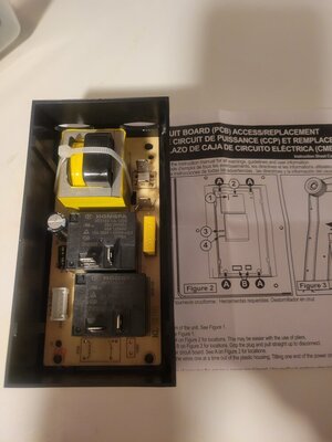
Circuit board
Over temp sensor
When re connecting circuit board my husband connect one wire not like how we took it off by mistake. But when connected wrong the bottom element did work but it them goes past the programmed temp and it shut off with an error.
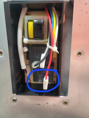
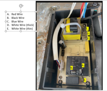
The circuit board it have 2 boxes im assuming they are relays one for top and one for the bottom. On the top there is a black and red wire connected. On bottom only a red wire connected vertically and nothing on horizontal. This is where hubby connected red on horizontal and got the element to work but not stop at temp. The instructions that came with new circuit box does not have this many wires in its diagram. Should there be a wire on that horizontal prong?
Any help?? Why we cant get this suckered to work properly?
We have not tried replacing the controller yet could that be a cause of problems?
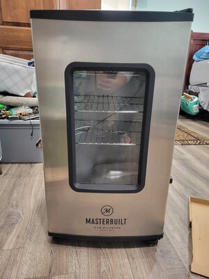
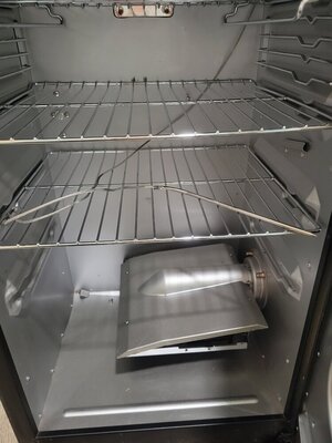
Pictures of unit attached. Also pictures of circuit board.
Element
Circuit board
Over temp sensor
When re connecting circuit board my husband connect one wire not like how we took it off by mistake. But when connected wrong the bottom element did work but it them goes past the programmed temp and it shut off with an error.
The circuit board it have 2 boxes im assuming they are relays one for top and one for the bottom. On the top there is a black and red wire connected. On bottom only a red wire connected vertically and nothing on horizontal. This is where hubby connected red on horizontal and got the element to work but not stop at temp. The instructions that came with new circuit box does not have this many wires in its diagram. Should there be a wire on that horizontal prong?
Any help?? Why we cant get this suckered to work properly?
We have not tried replacing the controller yet could that be a cause of problems?
Pictures of unit attached. Also pictures of circuit board.