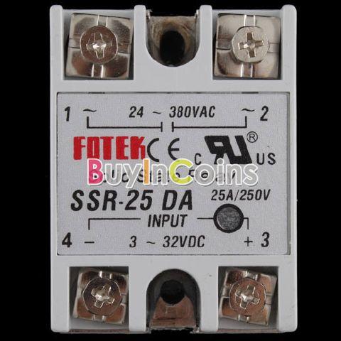
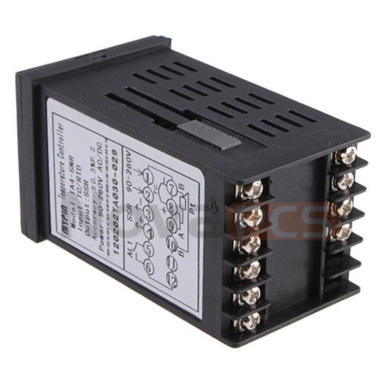
From the model info in the photo, you have a MYPIN TA04-SNR unit with the following configuration:
- TA = Model TA
- 0 = 85-265v AC/DC power requirement
- 4 = Size "4" housing
- - or blank = TC/RTD types are selectable from K J E S T B R Pt100 CU50
- S = Output #1 is SSR control signal of
- N = No output #2
- R = Alarm output is relay (switched only)
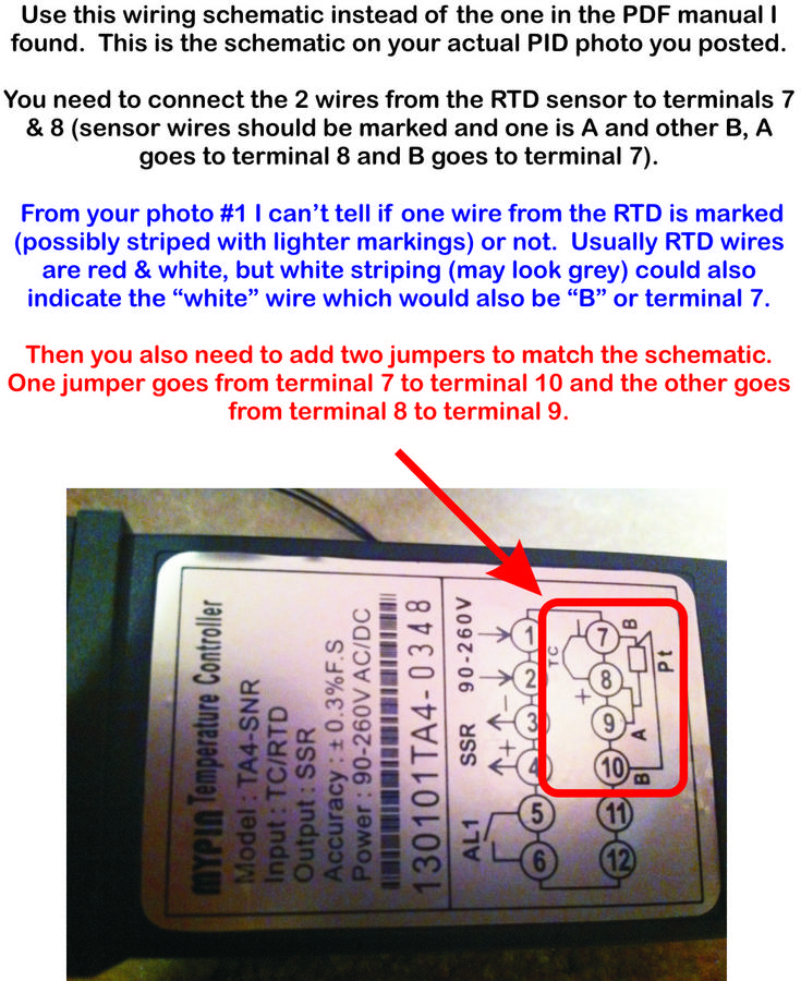
First question is what type of temperature probe do you have? The MYPIN TA4 uses a digital configuration menu where the sensor type of the probe must be set correctly along with other parameters. Examples of the probe types are K type, J type, etc.... The factory setting for a TA4 is "K" type and if you have another type of probe you need to change this to match what you have in the digital setup menu. Another issue might be the range of the probe you have. If it is a very high temp probe it may not read properly in ice water. So we need a little more info on what you have.
Double check the probe wiring also. Most probes are polarity sensitive but should be marked or color coded in their wiring.
There is a temperature offset value setting for the TA4 to correct an erroneous reading of up to 100*. It's the PVF setting in the configuration menu. If your setup for sensor type is correct, try changing the offset value to correct the reading. For example if the 70* reading is with the probe polarity wired correctly and reading ice water temps, then you need a -38 offset value to be entered into the configuration menu for PVF (70-38=32). Then test in boiling water and at a few other temps against a known good thermometer such as a Thermapen if you have one.
Here is a link to the English version of the Chinese TA4 manual
http://www.sanyoutech.com/UploadProductPic/200991715182749860.pdf
I found a link to a TA4 setup guide someone else has made on the web. It seems to be considerably better written than the paper manual from China I found. It's for a complete control module (plug and play), but that unit uses the TA4 as the PID so the steps and configuration process should be the same. Here is the link. This is on a FTP server.
ftp://65.74.99.15/Public/JConn Inv/PID Documents/PIDInstructionManual.pdf
***** NOTE *****
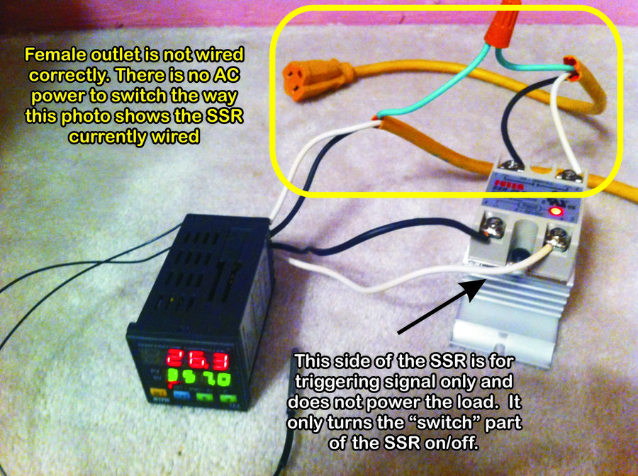
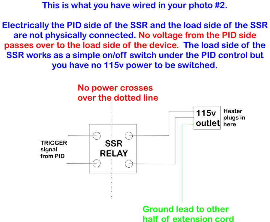
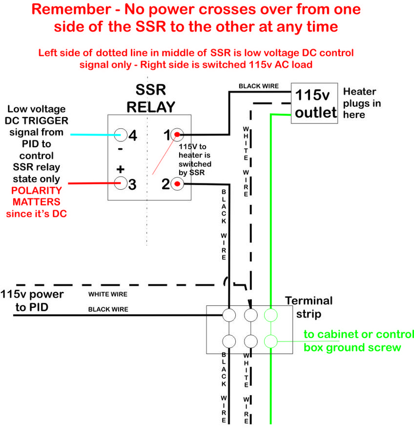
I see a major issue with your SSR wiring in photo #2. As is, it will not be powering anything.
I looks like you have the PID output to the SSR wired correctly, as in photo #2 the process value (desired temp) is set to 357* and the current temp is showing 26.3* and the output #1 LED is lit showing their is triggering output to the SSR. I take it you have it set for degrees C instead of F in the configuration currently (26.3* C is 79.34* F so that fits in the range with what you posted about the probe offset issue if you just took it out of the ice water recently)? So using the assumption you just need to adjust the offset value as described above, the PID to SSR side of the circuit appears to be working properly.
Ok, back to my wiring issue observation....
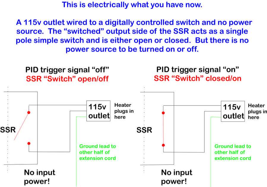
Remember that output from the PID is a low amperage triggering signal to activate the SSR only and does not power anything on the output side of the SSR. Since the LED on the SSR is lit, it shows the SSR is triggered and the solid state "relay" on the other side of the SSR is "closed" and would be completing the circuit on that side of the unit acting as a switch only.
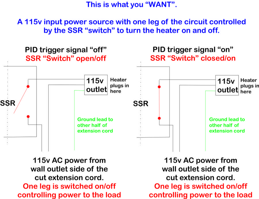
Problem I see is you have the female outlet portion of the cut extension cord wired there (on the output or "switched" side of the SSR), but there is nothing to switch the way that outlet is wired now. There is no power input on the controlled side of the SSR being switched by the SSR in your photo and in essence it's just the cut end of the extension cord hanging out in limbo. You need to think of the SSR like a single pole switch (basic switch) that goes in one leg of the AC power that should be going to that extension cord end. When the SSR is not active, the "switch" is open and no power flows to the load (heating element), when active the "switch" is closed and the power flows so the heating element turns on.
Be very careful when working with 120v AC as this stuff can injure or kill if done wrong (and quickly too). If you are not certain about your abilities, seek help.
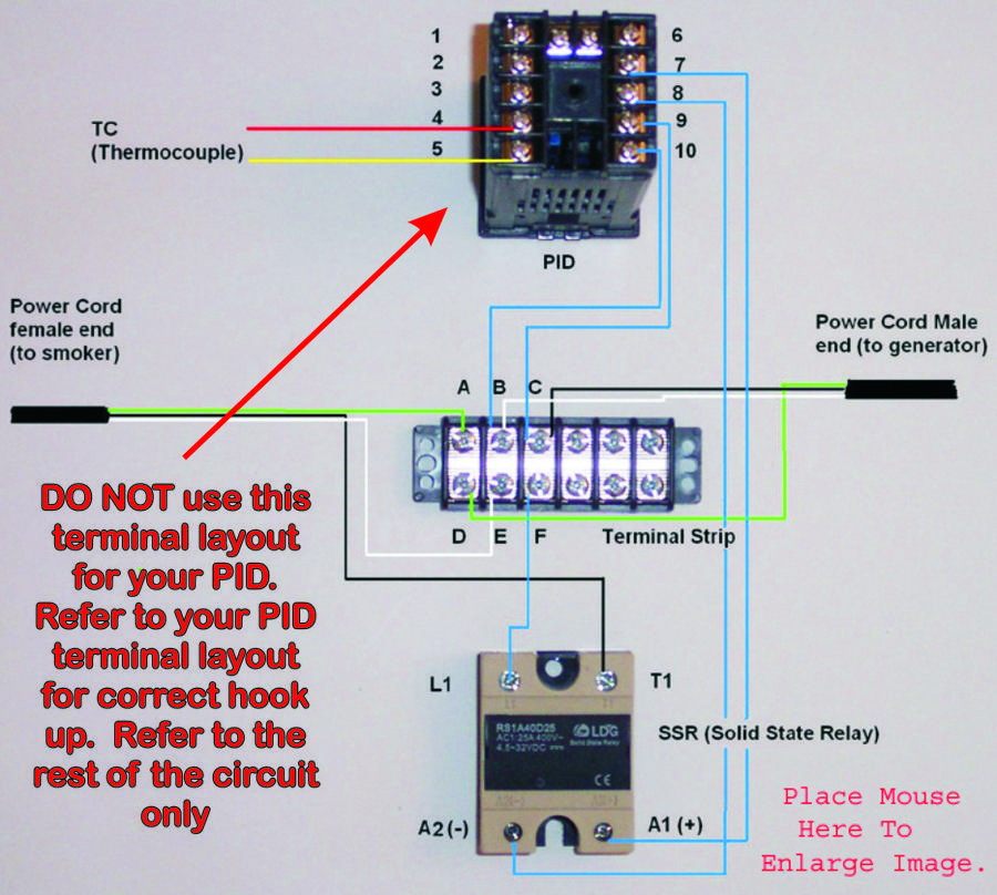
You need something similar to this
(IMPORTANT NOTE*** This PID has different PIN out terminals than yours. Use the pin out for your model, but refer to the rest of the image for a sample of how to provide power to both the PID and the load side of the SSR which is switched on/off.