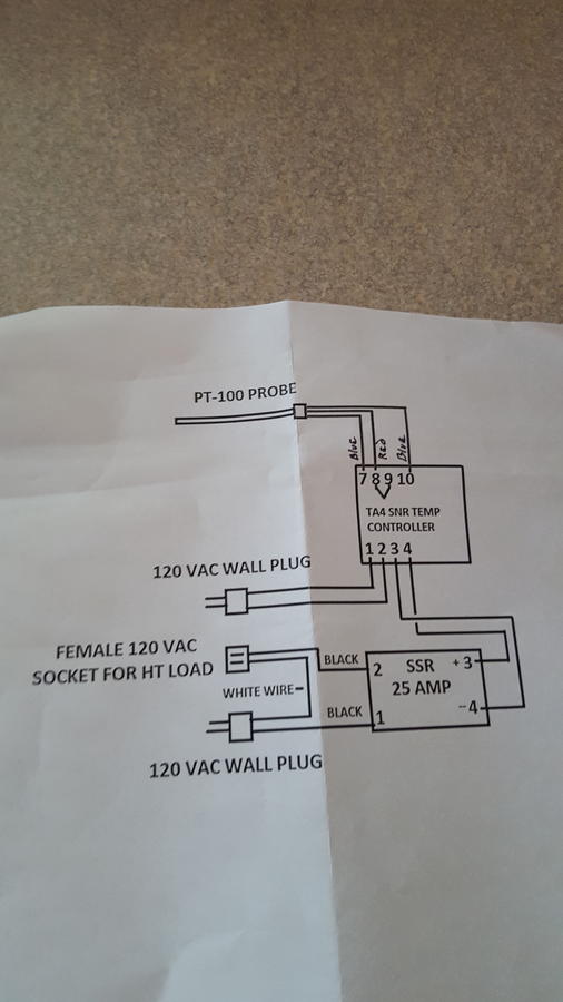
MYPIN TA4 PID manual, programming instructions and general PID/SSR info - by request

  • Some of the links on this forum allow SMF, at no cost to you, to earn a small commission when you click through and make a purchase. Let me know if you have any questions about this.
SMF is reader-supported. When you buy through links on our site, we may earn an affiliate commission.
Has anyone had any issues with the controller not reading temperature accurately over a range? I have two of these controllers that I'm trying out and both have issues with accuracy on temperature. Even after entering an offset, they still both drift off after heating up. Not just a few degrees... Like 15-20 degrees off. I build control systems for a living and have really never ran into an issue like this unless the controller or thermocouple is bad... Having two showing the same issues doesn't seem like just a one-off bad unit. Since you guys seem to be the only folks discussing this controller on the net, I thought I would reach out and see if this is a common issue with this specific manufacturer.
Try and run another autotune cycle from a cold pit.  The calculated "PID" formula may be off a little or the overall conditions may have changed (autotune run in winter where it was harder to hit target temp might cause it to overshoot in summer if the pit is not highly insulated is one case I can think of.  Another example would be autotuning for one temp and then changing to another setpoint temp later and expecting the same performance, you need to autotune for each desired setpoint if you are changing the temp more than a few degrees).

I would step through the current settings and write them down.  Then try a autotune from a cold pit and write those settings down.  They try another autotune from the hot pit and again write them down.  I suspect the happy medium can be found.   **IMPORTANT** make sure you program in the desired setpoint before starting each autotune. 

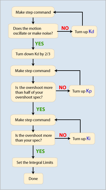
If you want to try and fiddle with the settings manually, here is flow chart to give you some directions on what to change.  Kd is the "D" value, Ki is the "I" value, and Kp is the "P" value.   P can be described as the present error, I would be the average of past errors, and D is system prediction of future errors based on prior performance.


If you are making manual changes, only change one value at a time and see how the change affects the system performance.  Make sure to give the system time to settle down before making a decision to make another change.  I would double or halve the value being changed as small changes have small effects.

Here is another chart that may be of help, but in the end it is sort of trial and error to manually tune a PID.
Parameter IncreasedRise TimeOvershootSettling TimeSteady-State ErrorStability
K[sub]p[/sub]DecreaseIncreaseSmall ChangeDecreaseDegrade
K[sub]i[/sub]DecreaseIncreaseIncreaseDecrease SignificantlyDegrade
K[sub]d[/sub]Minor DecreaseMinor DecreaseMinor DecreaseNo EffectImprove (for small K[sub]d[/sub])
 
Last edited:
 
Try and run another autotune cycle from a cold pit.  The calculated "PID" formula may be off a little or the overall conditions may have changed (autotune run in winter where it was harder to hit target temp might cause it to overshoot in summer if the pit is not highly insulated is one case I can think of).
Thanks for the comment.  No, not an autotune problem.  Just tried these out on the bench a few days ago using the standard ice bath/boiling water calibration method.  After setting the offsets for temp calibration, I installed both controllers on separate heated water systems, ramped the systems up to temperature, and then rechecked the actual temperature of the bath with a separate temperature reader... both controllers read much higher than the actual bath temperature.  Very odd, but I suppose it could be a wiring issue as some of the previous posts suggested that the wiring diagrams could be off vs. reality.  I'll let you guys know what I find out on Monday... maybe this well help some other folks experiencing the same issues with this controller. 
 
Sounds like oscillation in the process.  Try decreasing the derivative value (D).
 
I just want the parameter settings from the mypid, all I'm doing is turning on a fan when its cold, and off when its up to temp. the wiring is fine. my TA4 and SSR is only running a fan, (if it ever works). I have a second controller on the way, just in case I'm not crazy and the PID output that is supplying 30VDC no matter what the output led says is malfunctioning.
 
ok it was a bad mypid now its working but I want to have it turn on the fan whenever it drops below temp right now if it gets close dropping below temp the fan starts pulsing and over shoots the temp so I want my drift to be between 225- 230 so 225 fans on 230 fans off 
 
I am amazed by the amount of electronics/computer knowledge on this form. I am hoping that someone can help me or confirm my diagnosis or fix my new TA4 SNR.I suspect that the TA 4 is bad.

I have the TA4 wired to a SSR 25DD 25 amp. As soon as I energise the TA4 the SSR turns on. If SV is less than PV the controal voltage to the SSR is 3.3 volts. If SV is greater than PV the internal relay in TA4 clicks but the control voltage is the same. The Output Mode is set for 001=SSR.

Alarm one also does not work except for the internal TA4 led. Time for the big hammer???:wife:

I hope I don't have a sick one but I think so.
 
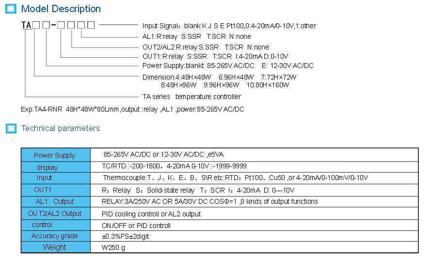
Should not be an audible "click" with an SSR output.  What is your MYPIN TA4 configuration number (model number).  Post the full info and I'll try and decode it. 

Should be something like TA4x-Sxxxx  (if it's not "S" for the first character after the dash that may be the problem).  That is hardwired into the unit and just changing the code to "001" for CTL type does not mean it will work.  It all depends on what variation of a TA4 you have.

Here are the configuration codes (click to enlarge)

 
Last edited:
My unit is a TA4-SNR. The relay click turned out to be the alarm which also does not have a signal out.

I Have been in communication with MyPin China by Skype, email and messaging. They had me do numerous tests on the unit. One of the things they wanted was the open circuit voltage from pins three and four without the SSR connected. I showed them that with output one light on the voltage read 23.64 volts which they said was normal. When I gave them the results for output one light off which was 23.72 volts I don't think they believed me. On Skype they mistook the alarm LED for the output one LED and this was the cause for their confusion.

I emailed them pictures of the test that clearly showed the LEDs on and off and also had the voltmeter in the picture. They quickly replied and confirmed my diagnosis that the unit was bad.

The Skype experience was fun trying to understand the girls English with a technician that was speaking louder in Chinese.

Thanks for your reply and perhaps this post will help someone else.
 
Is there any way to make the TA4 run on 220? I have not read all these threads as yet, but am hoping to find an answer to this. Thanks for all the info you have posted. It does help a lot.

buffalo47
 
If you look at the specs on eBay they call for power supply of 90 to 260 volts AC or DC. So should work.
 
I would not recommend this unit. I will likely be returning mine. It is reading 16 degrees too cold and there is not way to add to the offset, only to subtract. They admitted it's a bug in the software that they forgot to add addition functionality.
I have been using ta4 ta7 and td4's for years in the homebrewing world and I dont know where you heard that there is no place to adjust for the temp probe being off but their is. (whos they? you called the manufactuer in china?)  You can add and subtract although if your probe is off by that much then either it is defective or you didnt set the probe type to match the correct probe type that your using... there are rtd (pt100) and various thermoucouples like the "J' type out there.. if you never selected the right one your settings would be off...

These pids work very well actually and are capable of a shorter cycle time than the units from auber (which are also made in china BTW)

you can also buy the standard auber units direct from china for $30 shipped... they are often sold as the XMT-612 unit...
 
Last edited:
 
Sorry, I meant TD4, not TA4.
td4 and ta4 are indentical except for 2 things... the terminal layout on the back is moved around and the td4 has a manual pwm mode and the ta series does not... they also come in dual alarm mode or single or for driving mecanicall relays or ssrs... the dual alarm is niice because you can set a high and low temp threshold were the alarm will go off if somethings wrong.

and yes the mypins actually run on 24v dc so they have a built in powersupply which takes any ac power between 90-260 and automatically converts it....
 
Last edited:
I am amazed by the amount of electronics/computer knowledge on this form. I am hoping that someone can help me or confirm my diagnosis or fix my new TA4 SNR.I suspect that the TA 4 is bad.

I have the TA4 wired to a SSR 25DD 25 amp. As soon as I energise the TA4 the SSR turns on. If SV is less than PV the controal voltage to the SSR is 3.3 volts. If SV is greater than PV the internal relay in TA4 clicks but the control voltage is the same. The Output Mode is set for 001=SSR.

Alarm one also does not work except for the internal TA4 led. Time for the big hammer???
wife.gif


I hope I don't have a sick one but I think so.
you have to have a load on the ssr or it wont swithc correctly... most use a lightbulb to test but hopefully your ssr draws enough amps for the ssr to work... although you should get more than 3.3 v to the ssr... more like 24v when turning it on..

and you did wire the alarm correctly to the pid right? remember the alarm function is just a switch... you have to feed the power "in" and "out" to your separate alarm for it to work...
 
 
Tim,

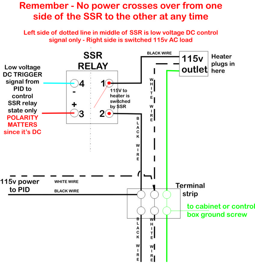
The PID only outputs a control signal and does not power a load.  You need a power supply feeding power to a SSR or relay (depends on what variation of the TA4 you have as to which).  The SSR or relay acts as a switch that is controlled by the PID (ie, flipped on or off).  The power supply through that "switch" is what powers your fan, heating element, or whatever else you have.

***Also if you have a SSR output PID and you connect a VOM across the load side terminals of a SSR with no load side voltage on the SSR, you will not see the SSR "close" the circuit when the PID triggers it.  It needs a load of some sort and voltage for the SSR to function.  This creates a feedback loop inside the SSR which is needed to make it work.  So don't panic if you have a SSR that does not seem to be working if all you have connected is a meter looking for continuity on the load side of the SSR.  If the LED on the SSR is coming on, try connecting voltage and a small load to the output side and it should work just fine (a small 120v lamp usually works for a PID & SSR that will be controlling a heating element).

In theory the SSR does the work of a plain old relay, but in actuality there is more to the equation to make the digital circuits inside the SSR work (it needs voltage and a small load to form the feedback loop).

Here is a diagram I made for another discussion with a forum member to help illustrate how the SSR works.  In his build, he controlled a outlet, but you can change that out for a heating element or other 110v load.  The key thing to remember is no power from the PID crosses over to the load side of a SSR at any time (the PID does not power the load).  There is no true "switch" inside a SSR as it's all digital logic circuits and no mechanical switch.  The concept of how the output side of the SSR performs is best illustrated by a "switch" though.

if I had a nickel for every time someone wired them up wrong and then blamed it on the "{cheap chinese pid or ssrs )"I would be rich by now.
 
Last edited:
 
if I had a nickel for every time someone wired them up wrong and then blamed it on the "{cheap chinese pid or ssrs )"I would be rich by now.
And to complicate matters even more there are PID's with dry contacts and other triggering circuit output that are not compatible with DC SSR's.  The companies usually make the different models and puts them in the same PID body. If you set them side by side they all look the same.  It depends on the factory internal configuration, which is why the full model number and the key to decode the specifications is important.

I have one Omega PID that triggers a mercury wetted relay to control a 10,800 watt heater bank in a commercial textile dryer for screen printing.  That one outputs 110vac as the triggering signal to the relay which then switches the substantial 220v load.   And yes, running that sucker will make your power meter spin real fast (roughly 50 amp draw at 220v when fully on).

Yeah, I know mercury wetted relay is old school - I will change it to a SSR if it ever dies, but it will also mean changing out the PID and adding a significant heat sink.  It ain't broke, so I ain't fixing it.
Yes even these mypins come in mechanical relay form as well as ssr models. The cheap ebay/amazon sold "rexC100 pids are often misrepresented as ssr pids .. Some sre but I here of many being sold the wrong type and having to mod them by removing the relay.

I actually service large wide format flatbed uv printers and newpaper CTP machines with pids and ssrs so I've been around them a while but it wasnt until I built my electric brewery that I really started paying attention to how they work.
 
Last edited:
I love the Mypin devices. I find most contain sayno parts. Several builds I have used the Mypin ta4, and just finished one with a ta6. I simply turn off the P and give it a ctl command for lenth of relay hold time and let it auto tun after box is up to temp. The devices that serve a purpose well.
 
  • Like
Reactions: docburns22
SmokingMeatForums.com is reader supported and as an Amazon Associate, we may earn commissions from qualifying purchases.

Latest posts

Hot Threads

Clicky