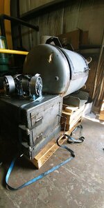
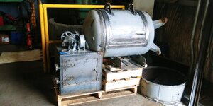
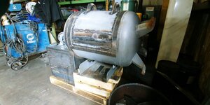
63.3 Gallon RF, nearly complete

  • Some of the links on this forum allow SMF, at no cost to you, to earn a small commission when you click through and make a purchase. Let me know if you have any questions about this.
SMF is reader-supported. When you buy through links on our site, we may earn an affiliate commission.

Malcolm B

Newbie
Original poster
Jun 27, 2019
24
9
Ontario, Canada
I'm back again. My last post here was on September 19 of last year and I was getting some technical input from you guys on my build. It has been nearly a year, but it's now about 90% done, the rest of which is purely cosmetic.

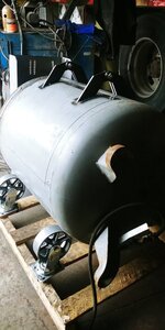
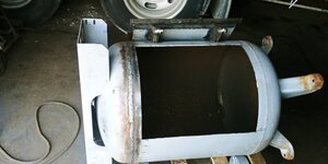
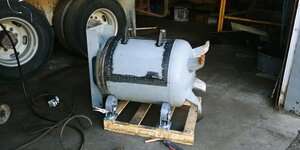
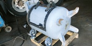
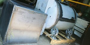
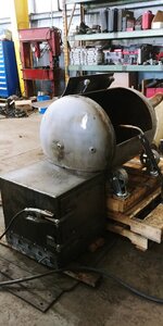
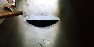
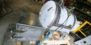
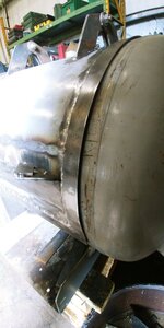
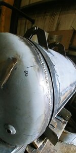
My project started life as an 80 gallon vertical air tank and was all that I could get my hands on for a reasonable price. 80 gallon was a bit too much for my requirements. I unfortunately had to cut it down, which was no easy task but it miraculously came back together as a 63.3 gallon, and squarely at that.
20190703_172834.jpg


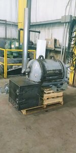
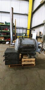
Here is the final product. I've been documenting as much as possible during the build. If I had to guess, I probably have around 150 to 200 hours into it. This week I'll be bringing the barbecue home where I can begin the sealing process of the paint and the testing stages of the barbecue. I already had it cooking once, but without cross flow vents as recommended by Daveomak and without the rain cap I fabbed up. Rest assured, there will be more pictures to follow and a more detailed break down of the build, but this is just to get the thread started!
20200418_142522_HDR~2.jpg
 
20190727_101045.jpg
20190727_101045.jpg
Thanks! And as promised; here is the beginning of the transformation.


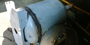
20190720_100207_HDR.jpg As I said, I took about 9"of the body of the tank to bring my volume down. I eventually did this with oxy-acetylene torches with plenty of practise on scrap pieces to twice slag build-up on the cut. It want perfectly square so I used a couple guide plates that I welded to the body to locate the capon reinstallation. I squared the cap off by measuring the four corners of the air compressor mounting bracket at the top of the tank, to the ground.


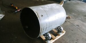
20190727_101034_HDR.jpg I laid the tank on it's side on a skid with four casters to rotate it and weld it evenly. Used the stick welder for this, but most of the rods had too much moisture. The welds were porous. I ground them down and went over top with some Mig wire to clean it up and seal the weld.


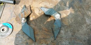
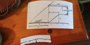
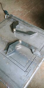
20190725_122323.jpg The hinges were made with bristol board templates 20190727_141928_HDR.jpg that I used to transfer dimensions and stack up to the fabricated pieces of metal. Before making the hinges, I marked out the dimensions and position of the door on the tank. I then cut the upper seam to commit the top of the door to the tank. I then continued with fabbing up the hinges. Once they were done, I tacked them together in two sets, drilled one hole through each set, bolted them together and welded them to the door and CC. 20190727_101045.jpg
 
Last edited:
By the way, I'll post as often as I can, but there's about 100 pictures and almost a year's worth of work. So it'll take a little while to upload it all.


20190727_150250.jpg The upper compressor mounting bracket and the legs 20190729_175533.jpg were left on so I could trace out the dimensions of the door and square it up to the rest of the tank. I cut the door at about 1/4 of the circumference of the tank, which I later changed after realizing that the opening for my firebox would only be about 5" from the bottom of the tank. There are a few things I learned throughout the build;

  1. Follow Dave's RF calculator, but don't try and have everything planned out to a "T" before you get to it. In this case, I should have focused more on the placement of the FB to the CC before committing to the door placement.
  2. Most of the stuff should be tacked on until you're ready to fully commit to the placement. Double, triple and quadruple check things before fully welding something in place. This will save you from tonnes of grinding/cutting later on.
  3. If you make a mistake, don't fret it. It can ALWAYS be undone. It might just take a little while longer.
  4. Don't be discouraged. This was no easy task, but the level of satisfaction you'll receive from the final product will be reward from the painstaking hours put into its construction.

20190729_175552.jpg The door proved to be a bit of a pain. Deciding where to place it and cutting the opening was the easy part. The difficult part was trying to get the door flanges to follow the curvature of the tank. I used the 9" section I cut away from the body to give me a guide for how much of a curve I needed. I initially welded the bars on, tacking and clamping one inch at a time, but the rigidity of the bars spread the door, causing there to be a gap in the bottom.


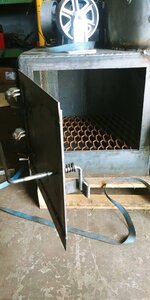
20190803_115742.jpg 20190803_115755.jpg The firebox was made from 1/4" plate, the same as the steel used in the construction in the body of the air tank. I religiously referenced Dave's RF calculator and the Dave's Reverse Flow Calculator and the link to the Circle Calculator to find the height of the cut required.
 
Hopefully you guys appreciate the detail in trying to provide. I don't have a good camera and didn't do a video blog of the process. If I'm missing something or you have a question, feel free to ask!

20190810_140720.jpg Similarly with the CC hinges, the firebox hinges were templated on bristol board and transferred to steel bar to be fabricated.


20190810_151406.jpg And again, the hinges were tacked on after the inside seam of the door was cut. Before the door is fully cut from the firebox, I had the door flanges in place keeping it from falling in.


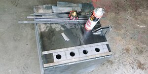
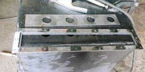
20190817_095724.jpg The vents were made from a strip of flat bar that slides in between a welded box. In this picture, I'm just showing the measurements on the bar in relation to the holes in the FB.

20190817_112419.jpg
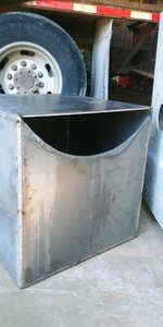
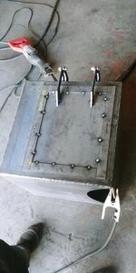
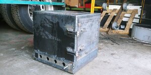
This is the box that the vent slides in. I used 1/2" flat bar around the perimeter of the vent door. I kept the door inside the box by welding on 3/4" flanges overtop of the 1/2" flat bar. All the holes you see were drilled in the inside of the box. I drilled through the 1/2" flatbar and partially into the 3/4" flatbar then filled the holes by welding them together. The door was put inside the box, mounted and tacked to the FB. 20190817_145542.jpg
 
I then decided to weld the FB to the CC. In hindsight, I'm probably doing things a little backwards. At this point in the build, I was probably two months in and wanted to see some light at the end of the tunnel. Message_1566667275246.jpg So I focused on joining the FB and the CC. It's steps like this that took a lot of time just trying to find the center of the tank and accurately measuring the opening. Don't kid yourself, you want to spend all the necessary time to get this right. Cutting the opening out of the tank is critical and can either make the job progress, or make a lot more work for yourself. Using the brackets for the compressor mount, I was able to find the tank center fairly easily. I found the outside diameter of the tank and used a piece of string cut to half the circumference to verify the measurements. Using the Circle Calculator helped me find the length of the opening, which I split equally at the center of the measurement for the circumference of the CC.

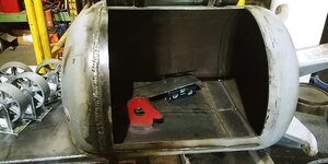
20190824_132208.jpg Both pieces had minimal gaps and assembled fairly easily. I used a level to make sure both parts were even, then committed with a few tacks on the inside, verifying the level on the CC and FB then fully welding both the inside and outside of the joint.
Message_1566669401909.jpg

Now some of you may have noticed the distance from the bottom of the CC door in relation to the top of the FB. Well that will be addressed later. It was something I overlooked but I'm publishing the whole project, - mistakes and all, so anyone reading can see that this endeavor isn't just puppy dogs and rainbows. It had it's frustrations too. Though I decided to focus on trying to keep the FB door shut.

20190831_115521.jpg 20190831_115616.jpg
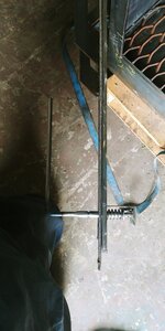
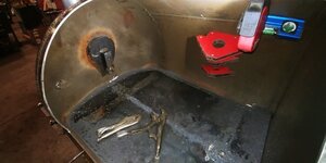
The non technical part of this door is the 1" angle iron bracket welded to the inside of the FB that this handle latches into. I sleeved the handle (1/2" rod) into 3/4" pipe. I wanted the handle to latch on two positions so this is where the spring comes into place, it allows tension to be maintained in both the open and closed positions. To hold it in place, I welded a piece of the 3/4" pipe to the outside of the door on the handle. (Before this was assembled I thoroughly lubricated it with anti-seize in the hopes of trying to avoid that problem through the winter).
 
Last edited:
Looks to be coming along nicely Malcolm! I'd assume the grate in the FB is removeable so you'll be able to shovel out the ashes inside. On my Meadow Creek SQ36 there is a steel drawer that pulls out with the ashes that have fallen thru FB grate making clean very easy. Is something like that in the cards or will you be using some kind of flat scraper to shovel the ashes out? RAY
 
Looks to be coming along nicely Malcolm! I'd assume the grate in the FB is removeable so you'll be able to shovel out the ashes inside. On my Meadow Creek SQ36 there is a steel drawer that pulls out with the ashes that have fallen thru FB grate making clean very easy. Is something like that in the cards or will you be using some kind of flat scraper to shovel the ashes out? RAY

Yes, Ray! The grate is removable. I had tried to figure out how and where to put the drawer for placement. I kept getting stuck on the design of it. I can only mount a drawer in the back of the FB, opposite the door. (Dimensional constraints overlapping the door and outer edges). I also couldn't quite get my head wrapped around how I was going to have a basket in there, that doesn't restrict air flow. And if I put a screen in place of the side of the basket, how much ash would fall out of the screen and into the bottom of the FB. I decided not to invest too much time into it to keep the project moving.

In the meantime, I will empty it with a shovel and a shop vac. I have thought about installing a pipe that I can slide a shop vac overtop of and turn on, then just sweep the ash towards the pipe inlet for simplicity. But I can worry about that later if the shoveling becomes too much of a nuisance.
 
20190831_115644_HDR.jpg I have previously mentioned that I saw there was an issue with the distance of the bottom of the CC door to the top of the firebox. This image shows that there was nearly 7" in between the top of the firebox to the bottom of the door. I decided to take the flanges off the side of the door and cut it lower. You'll also notice, that the gap in between the door and the body is enough to squeeze a semi through, and somehow it gets corrected but I'll speculate more on that towards the end of this update.

I'll remind you guys, that as I assembled the door, I was welding and clamping the flange about an inch at a time. I didn't try to form it before installing the flange. I tried grinding away a channel on the inside of the door, squeezing it together with a ratchet strap and drawing a heavy (and alternating from side to side) bead of weld to reduce the gap, but ultimately I decided to cut the flanges off and restart. I left the top flange in place then welded the bottom of the door back to the tank and cut further down the cook chamber. I believe I added about 4" to the bottom of the door, bringing the distance from the bottom of the door to the top of the firebox to around 2".

20190907_143014_HDR.jpg 20190907_143023.jpg


As you can see, this gave me much more area inside the chamber, plus it looks a lot more proportionate

20190907_143042.jpg 20190907_143053_HDR.jpg Before reinstalling the flanges, I tried bending them to the contour of the tank before welding them in place. As you can see, this provided a much better seal in between the door and the cook chamber. I think I went wrong in two spots;

1) This steel was cold-rolled, which makes it a lot less malleable than hot rolled.
2) When I welded the steel on, I believe the rigidity of it was actually pulling the door open.

There are two things you could do to avoid this on your project and that is to either use hot rolled steel for the door flanges, or if using cold rolled, pre-form it to the contour of the door.
 
Before getting to this step, I had spent most of my time trying to figure out if I was going to go the easy route and weld in a single piece of plate for the reverse flow baffle, or if I was going to make mine funnel towards a drain. Of course, I never like to do things the simple way, so I spent my time considering;

1) I wanted this smoker to last for years. Yes it would take a lot more effort, but I was willing to commit an additional 8-16 hours just testing, fitting and fabricating if I could spend it enjoying what I created, without thinking, "if only I made the funnel like I wanted, cleaning the baffle is such a pain in the butt."
2) How would I clean up food bits and waste without having a drain? I would have to scrape or shovel it out. This would be a huge pain trying to clean up smoky, greasy, waste if I couldn't just drain it and dump it.
3) Where would I position the drain pipe? Sticking close to the heat source was ideal, but I didn't want the end of the handle close to the firebox for when I go to drain it. Not to mention, I planned on using a ball valve for drainage which could end up melting the seals internally.

20190914_150251.jpg 20190914_150233.jpg


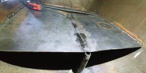
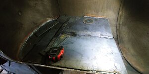
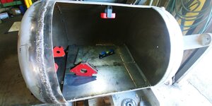
Creating the reverse flow This part was incredibly difficult and I can offer no explanation other than it took a lot of test fitting to make the pieces fit correctly. The first part was to use the circle calculator with the reverse flow calculator to determine the minimum size I'd need for the area underneath the reverse flow baffle. When I determined the height, I installed a threaded rod and welded it in place to secure my "minimum height" to encourage positive flow.

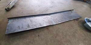
I then fabricated a cradle from some left over flat bar that I used to hold some templates in place while I made the correct adjustments, then transferred them to the 3/16" plate to be cut out and welded them into the cook chamber. From there was able to make the cap of the baffle, which I also tacked on 1/2" angle iron.

20190914_150303.jpg 20190914_153416.jpg


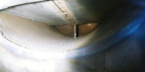
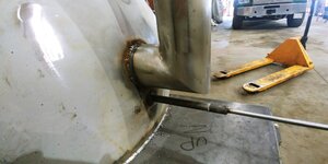
I welded most of the two seams together, but left the center of the four plates. I drilled a pilot hole then proceeded with a step drill to ream it out to the I.D. of the drain pipe. I then finished by welding all four plates to the drain pipe in the center.

20190914_153603.jpg View as seen from the inside of the firebox.


20190914_160526.jpg 20191005_153621.jpg Finished reverse flow baffle
 
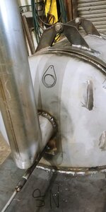
T 20191005_153750.jpg 20191005_153820.jpg Allow me to start off by reminding you that I don't often do things the easy way. I wanted to have a rain cap on the top of the chimney and couldn't think of a simple valve I could fabricate that would remain inside the exhaust stack. So I made the exhaust cap on the inside of the cook chamber. On the picture to the right, you can see where I drew a mock-up plate that I welded to the exhaust stack inside the cook chamber. The teardrop shape allowed me to swing the cover away from and overtop of the exhaust pipe. The larger circle is the exhaust pipe and the smaller one is the steel rod that control the movement of the plate. In my previous post on this thread, there is a good thumbnail of the inside of the cook chamber, with the plate and exhaust pipe.

20191005_153716.jpg 20191005_153734.jpg The exhaust stack was made from 4" O.D. pipe. I cut it to 36" above the top of the cook chamber.
 
SmokingMeatForums.com is reader supported and as an Amazon Associate, we may earn commissions from qualifying purchases.

Latest posts

Hot Threads

Clicky