PLEASE help on my PID build... photos and my connections

  • Some of the links on this forum allow SMF, at no cost to you, to earn a small commission when you click through and make a purchase. Let me know if you have any questions about this.
SMF is reader-supported. When you buy through links on our site, we may earn an affiliate commission.

thepackerbacker

Smoke Blower
Original poster
Sep 24, 2013
98
12
Appleton, Wisconsin
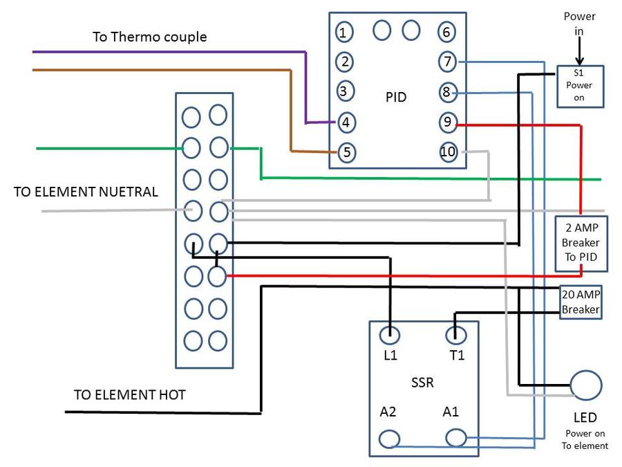
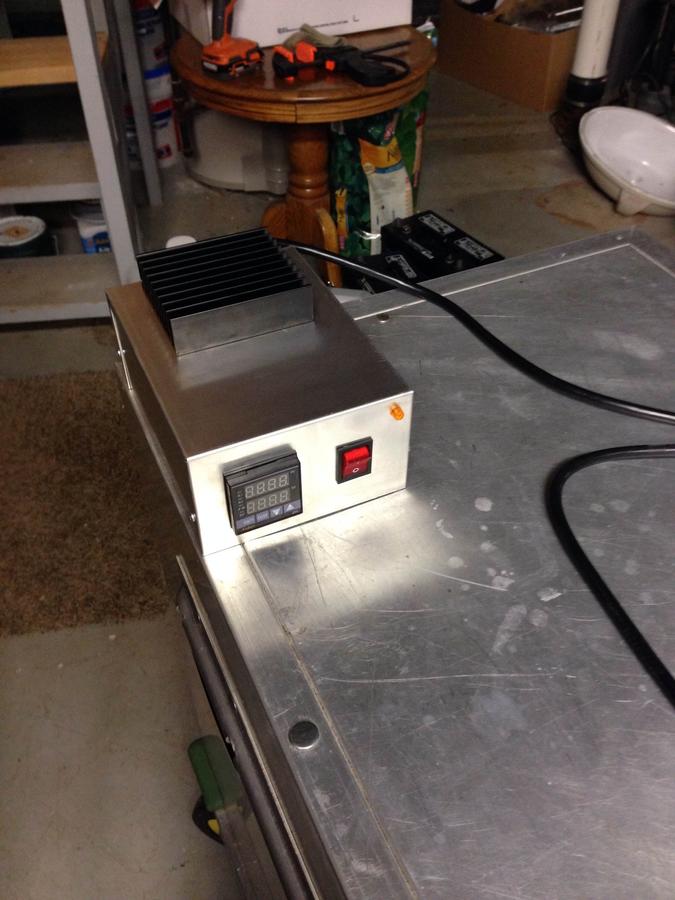
Okay, I have looked at no less than 10 different wiring diagrams/schematics. My eyeballs are burning after reading so many posts....and Im still not sure this is hooked up correctly. Is there anyone out there who can shed a little light on how to hook this thing up?

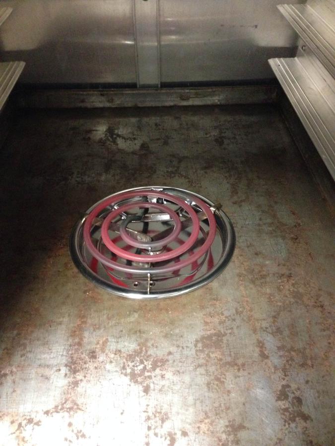
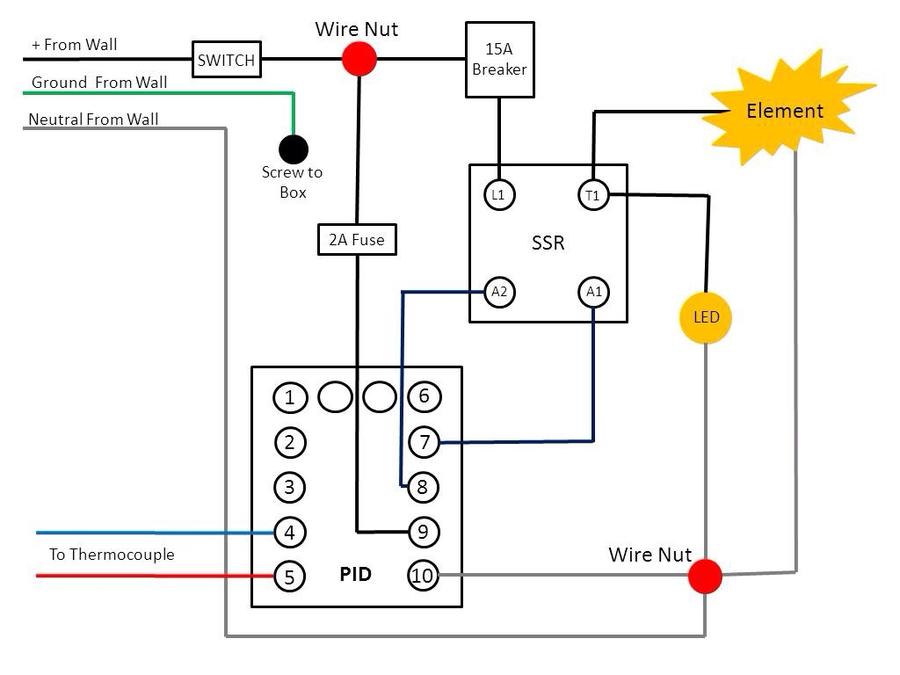
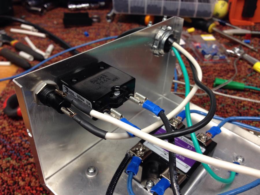
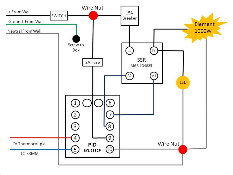
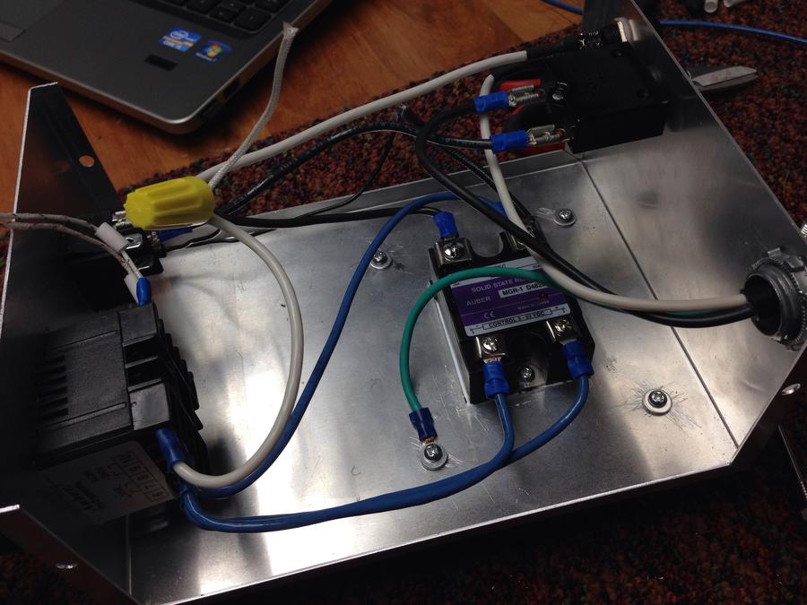
The white and black high-temp wires are where I would hook in the 1000w burner. The LED should be "on" when the burner is "on"

I want the whole setup switched. The burner should be protected with the 10A breaker and the PID should be protected by the 2a fuse.

So is this hooked up right or am I way off?

I am going crazy!!!


Last edited:
You can wire nut them together. I find that with stranded wire I can get a better connection with a lug crimped on. With solid wire I can twist the wires together with lineman pliers to make a solid connection. As long as your wire nut is as tight as possible should be fine.
 
Sure you can use wire nuts instead of terminal strip....so long as it is wired correctly. The drawing posted assumes a certain type PCU & SSR since pin numbers are designated. It may not work if pin numbers/functions are different on your stuff. I'd change the wiring on the large breaker to protect both the SSR and element. As pictured only the element is protected.

Hope this helps

RG
 
Sort of tough to desscibe in words...here goes. Trace hot lead from wall socket the first thing it should go thru is the large breaker then to the SSR then to the element. This is a series connection. The breaker will protect everything behind it. If you put the led on the element side of the SSR it will light when the element has power. If you connect led to A1 side it will lite when the whole unit has power. If you like lights you can install both.

Hope this makes sense.

RG
 
240 is pretty simple. What type of plug would you be using? Also need to know the specs for SSR. Or you could use 2 of the 110v ones. Let me know and I can draw one up.

RG
 
Iowa Josh,

Here is my first crack at using a 240vac element with this controller.  I am making a lot of assumptions here.   Not all PIDS

are the same.  They have many different configurations, ratings, pin numbers and functions.  This drawing assumes you

are using the EXACT  PID at the beginning of this post.  I used the same wire colors as in the original drawing. 

The "large breaker" value must be determined by your element wattage.  Just divide your wattage by 240 to get the element current.  example 1500w / 240= 6.25amps use a 8-10amp breaker in this instance.   

The SSR MUST be rated to handle a 240VAC circuit.  380VAC is a common one to use.   The element "on" indicator was

a bit tricky, I did not want to add to much more circuitry / complexity.  The "R" value is determined my the voltage output by

the SSR drive.  Measure the volts between PID pins 7&8 with no connections on them.  Take this voltage and

divide it by .005,  this will give you the R value in ohms. The value you choose does not have to be exact, just close. 

Higher ohms= dimmer , lower ohms=brighter.  1/4 or 1/2 watt rating on the resistor is fine. 

This is for use of a straight, standard LED, if is doesn't lite, flip it around.  LEDs have a polarity, (+/-).  They won't lite if put

in backwards.  Or you can forgo all this resistor stuff and use a light bulb rated for the voltage measured on PID pins 7&8.

If you are not familiar with electricity / electrical hook ups, please find a friend or someone who is experienced to assist you. 

This stuff can hurt and kill you if not properly done. 

Maybe some of the regular guys can comment / advise on 240 volt hookups.  I have never done one.  I am familiar with PIDS, power controllers.  I was wanting to build a digital  thermometer / high temp alarm for my wood fireplace insert.  I got to designing a discreet circuit read a lot on thermocouples/ offset reference amps)  and found a PID controller with thermocouple for $30 on Ebay.  A home-brew one would have been easily $100 plus time / fuss. 

God Bless,

RG

<<Edit>>   deleted drawing containing error. 
 
Last edited:
230v breaker should be across both legs of the 230v supply not just one as you have in the illustration.  It has two 115v legs like your switch. The way you show it in your drawing, the unprotected leg that does not go through the breaker (your drawing shows a single leg or 115v breaker and not a 230v breaker) would leave that branch side of the 230v circuit totally unprotected. 

Each branch inside your unit should be fused or have a breaker of appropriate size for wiring in that portion of the circuit.  For example if you have a 20amp main breaker and you have 22gauge wire feeding the PID, you will need a breaker or fuse sized to 22ga wire to protect that section.  Hence use of a smaller breaker or fuse for the PID protection.  You want the breaker to do it's job and trip before the wire starts a fire.  Small gauge wire will toast long before a 230v breaker opens.
dward51

Good catch on my error.  I took down that drawing and my the correction.  The rating (current)  for each of these large breakers should be remain the same. 

Divide your wattage by 240 to get the element current,  example 1500w / 240= 6.25amps total, 6.25 use a 8-10amp breaker. 

Sorry for any confusion this may have caused. 

RG
 
Last edited:
Are you using two separate breakers for what you have labeled as "breaker #1" and "breaker #2"?  It should be a single 230v breaker.  They way you have it drawn it looks like you have two separate devices.

If you are using a single 230v breaker, the drawing is somewhat misleading especially to those who may not be familiar with 230v circuits.   DO NOT USE TWO SEPARATE 115V BREAKERS TO PROTECT A 230V CIRCUIT.   I would put the 230v double pole breaker just ahead of your master power switch.  That way the breaker is the first component in the overall circuit and if the switch failed or a wire came unscrewed and hits the metal cabinet, it will ground out tripping the 230v breaker like it's supposed to.  Putting it after the switch makes the switch and the wiring prior to the breaker unprotected.

For those who have never worked with 230v circuits, the white or Neutral line is not needed for 230v portion of the circuit.  It is used however for the 115v tap on one leg of the 230v supply that will provide 115v to the PID.  And yes, it should be isolated from the chassis.  There should always be a ground wire in addition to a Neutral (which is show in the original drawing).

I would do it this way, or you can use a properly sized breaker in the distribution panel and remove the double pole breaker in the smoker.  Either way will work.

Not knowing the model and pin out of your PID and SSR, it appears to be generally OK now (assuming you have those two components connected properly)

 
Last edited:
Just thought I would post what I had used in case other have the same components and are trying to follow this post.

PID is SYL-2352P

SSR is 25A MGR-1D4825

Thermocouple is TC-K3MM
 
Also need to point out that my thermocouple was wired backwards!!! I was having issues getting the temp to read correctly and posted the dihlema in another thread. Ended up I needed to switched #4 and #5, the wires were backwards and are also backwards in my above drawing. I will update and post the correct schematics.
 
 
Are you using two separate breakers for what you have labeled as "breaker #1" and "breaker #2"?  It should be a single 230v breaker.  They way you have it drawn it looks like you have two separate devices.

If you are using a single 230v breaker, the drawing is somewhat misleading especially to those who may not be familiar with 230v circuits.   DO NOT USE TWO SEPARATE 115V BREAKERS TO PROTECT A 230V CIRCUIT.   I would put the 230v double pole breaker just ahead of your master power switch.  That way the breaker is the first component in the overall circuit and if the switch failed or a wire came unscrewed and hits the metal cabinet, it will ground out tripping the 230v breaker like it's supposed to.  Putting it after the switch makes the switch and the wiring prior to the breaker unprotected.

For those who have never worked with 230v circuits, the white or Neutral line is not needed for 230v portion of the circuit.  It is used however for the 115v tap on one leg of the 230v supply that will provide 115v to the PID.  And yes, it should be isolated from the chassis.  There should always be a ground wire in addition to a Neutral (which is show in the original drawing).

I would do it this way, or you can use a properly sized breaker in the distribution panel and remove the double pole breaker in the smoker.  Either way will work.

Not knowing the model and pin out of your PID and SSR, it appears to be generally OK now (assuming you have those two components connected properly)

My proposed 240v built will have the heat element/blower in a separate box and wired to the pid/controller box. If I run wires from the 2 ends on the element to a TB inside the pid/controller box and conect it where you have the 240v element, will this work?
 
Down,

That will work fine. Dont know your wattage if it's just a few feet it'll be fine. A longer run might need a fattet wire. Msko sure to protect it from heat and weather.

RG
 
SmokingMeatForums.com is reader supported and as an Amazon Associate, we may earn commissions from qualifying purchases.

Latest posts

Hot Threads

Clicky