- May 10, 2018
- 100
- 277
Update 1/9/19:
In posting and talking with other folks there is some confusion on what we commonly call a "curing chamber" when it actually a drying/aging chamber.
Curing is the 1st step in the process followed by the drying and aging process.
I have gone though this thread and changed "curing chamber to drying/aging chamber or D/A chamber.
I hope this thread inspires folks to build their own drying/aging chamber or at least this thread is that little push for other's who were the fence about building a drying/aging chamber.
The whole idea behind a drying/aging chamber is having the ability to mechanically replicate a naturally occuring environment. Not many people live in environment that is naturally perfect for curing/aging meats. Even those who are most likely these conditions are seasonal and not year long. So if curing/ageing meats or cheeses is something you want to do and you do not have the right natural conditions its time to build a D/A chamber. In a chamber you need to control 2 things. Temperature and humidity. To do this you need to be able to
Appliance you'll need to convert into a curing/aging chamber:
Refrigerator, beverage cooler, freezer or wine cooler (This is the cooling and chamber body)
Note: If using a upright freezer the type with cooling running through the shelves/racks will not work. It must be an open style. Also wine coolers are typically too small.
Then you will need the following all available off of Amazon. Prices are as of 11/14/18:
Inkdird IHC-200 = $34.99 (this will control the humidifier and dehumidifier the chamber)
View attachment 380421
Inkbird ITC-308 = $39.99 (This will control the cooling and heating in the chamber)
View attachment 380420
Crane "Drop" 1 gallon humidifier = $39.99 (This will add moisture when needed)
View attachment 380422
Eva0Dry-1100 dehumidifier = $37.45 (This will remove moisture when needed)
View attachment 380423
Honeywell HCE100B ceramic desktop heater = @21.18 (This will add heat when needed)
View attachment 380424
Note: There are other humidifiers, dehumidifiers and heaters that will work. You must make sure that they have manual on/off switches. Push button electronic lo/med/hi or digital switches will not work. The equipment must always be mechanically in the "on" position or always "enabled" to run. The Inkbird controller will take care of turning the equipment on/off
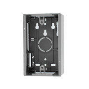
Now that you have the chamber body , controls and equipment you will need a way to get the power wires from inside the chamber to the outside. This can be accomplished several way. I chose to add three (3) single gang surface mount 120v outlets to the interior of the chamber and then extend the wires through the chamber wall to the exterior.
Note: If mounting electrical boxes to the interior do not be tempted to by a 3 or 4 gang box. Since some of the equipment has a big plug on it you will not be able to plug stuff in side by side. Using single gang boxes spaced an inch or so apart overcomes this.
Electrical hardware you'll need:


Now onto the interior layout of the electrical boxes.
1. Verify the chamber is unplugged.
2. Determine what wall you want the electrical boxes on and verify there is no wiring, drain lines or refrigeration piping in this wall.
3. Next draw three (3) vertical pencil lines from the floor of the chamber up about 8 inches. Then left to right space the lines 3 to 4 inches apart.
4. Next come up from the bottom of the chamber 6 inches and make a level line across all three vertical lines. This will be the center of the electrical boxes and where you will drill the holes for the conduit to exit the chamber.

5. Where the three lines intersect drill a 1-1/8 inch hole through the wall of the chamber. This for the conduit to go through.
6. Punch out the 1/2 inch knockout out of the back of the backbox, put the male adapter in the backbox and thread the conduit nut (conduit nut goes inside the box and the smooth socket of the male adapter is on the back of the back box) on to secure the male adapter to the backbox. Repeat for all three boxes.
7. Next place the back box in the chamber with the male adapter centered over the 1-1/8 inch hole and push tightly against the chamber wall. Make sure the box is plumb/level then secure with sheet metal screws in the provided mounting holes. Repeat with all three back boxes.
NOTE: When using sheet metal screws to secure the back boxes it is a good idea to mark the mounting holes with pencil, remove the box and drill a 1/16 inch pilot holes. Then replace the box then fasten with the screws. Two screws per box is sufficient.

8. Now on the outside of the chamber push the 1/2 inch conduit through the side wall and into the socket of the male adapter in the back box. Make a pencil mark on the conduit flush with the exterior of the curing chamber wall then pull the conduit back out. Measure from the end of the conduit to the pencil mark. Cut 3 pieces to this length then insert all 3 pieces into the back boxes. This little section of conduit will act like a sleeve through the chamber wall.
9. Cut the extension cord into three sections (I like to go with extra so 7+ foot) piece to be trimmed to suit later.
10. Strip back the rubber outside sheathing on one end of the cord to expose the 3 wires contained within. Then strip back the insulation on the individual white, black and green wires.
11. Wire the duplex outlets White wire to silver screw, black wire to brass screw and green wire to green screw. Repeat for all three duplex outlets.
12. After the duplex outlets are wired pull the wiring through the backbox until the outlet is seated in the back box. Secure the outlet to the backbox with factory supplied screws on the outlet then install the cover plate. Repeat with all three outlets.

Now with power boxes installed time to move to the outside of the chamber.
13. Gather the 3 PVC 90's and cut 3 piece of 1/2 inch conduit approximately 8 inches
14. Now thread the tail of the wiring through the 90 and push the 90 over the wall sleeve in step 8. Repeat with all three wires.

15. Now thread the wire through the 8 inch pieces of conduit and push into the top side of the 1/2 inch 90.
16. Verify the 1/2 inch risers are plumb then about an inch down from the top secure with the 1/2 inch conduit strap. Once secure seal the gap between the wall of the riser and the wiring with silicone. If you don't seal then gap in the summer hot humid air will settle in this gap then condense and water will run in the chamber through the electrical box.

17. Wire on the male plugs to the three cords that are extension's from the interior electrical boxes. These plugs will get plugged into the controller 120v female outlets.
18. Next onto locating the Inkbird controllers on the exterior of the chamber. I like to put them with the digital display at or near eye level. Once you have them where you want them at the top of each controller is a tab with a hole in it that you use a screw to hang the controller on.

NOTE: If you are not absolutely sure of the controller placement you can use some double sided tape to temporarily mount the controllers. Then once you are satisfied with the location then use a screw to fasten them to the chamber wall.
19. Out of the bottom of the controllers are the 120v "function" outlets that will power the interior outlets. Pull these plug ends down to straighten out the wire and secure them the the outside of the chamber with double sided tape or there are also slots in the back that you can install small screws int he chamber wall then slip the plugs over to secure.
20. Next step is to drill 2 additional small diameter holes in the side of the chamber. One is for the humidity sensor the other is the temperature sensor. Seal around these holes as well ideally with something removable like a heavy duty tape or pliable putty to keep air out.
NOTE: You will have to measure the temperature sensor and humidity sensors to determine wheat size holes to drill. Mine were 1/2 inch for the humidity seanor and 1/4 inch for the temperature sensor.
21. Slide the sensors through the holes and into the interior of the chamber. Secure the humidity sensor about 1 inch down from the ceiling of the chamber with double sided tape. The Temperature sensor is also installed up high and not in the direct path of the condenser fan. Also make sure the temp sensor metal bulb is not touching anything just hanging freely.
22. Now its time to start plugging equipment in. The controllers each have a duplex plug with each plug perfuming a different task.
Temperature controller plugs are marked:

24. Now plug your "extension cords" coming from the interior of the chamber to the corresponding controller plug. Then plug the refrigerator into the "cool" plug the remaining three (3) plugs, plug into the outlets as outlined in step 22.
25. Fill the humidifier with water
26. Turn the refrigerator to the coolest setting.
27. Plug the Inkbird controllers to the 120v wall outlet and the controllers should light up. Now it's time to program the controllers and get the chamber up, running and controlling cooling, heating, humidifying and dehumidifying.
I run my chamber at 57 degrees and 80% relative humidity with a 2 point dead band.
NOTE: Dead band is an range plus or minus of set point. If you set the chamber at 57 degrees with no dead band when the temp rises to 58 degrees the cooling will run until it reaches the 57 degree AKA setpoint. But it will also overshoot and cool past 57 degrees to 56. Now that you are below setpoint the heat will come on to combat the over cooling. Then just like the cooling when the 57 degree set point is reached the heater shuts off but will overshoot to 58 degrees and the cooling kicks back on. Its a vicious cycle that will have the heat and cooling fighting to maintain a finite setpoint. To combat this if you add in few degrees of dead band now when the chamber is set at 57 degrees but the cooling will not kick on until the chamber reaches 60 degrees. So now at 60 degrees the cooling kicks on and at 57 degrees it shuts off and can over shoot to 54 degrees before the heat will kick on. Dead band simply allows newly introduced conditioning time to settle.Your home heating or cooling had dead band built into it from the factory.
This is how my Inkbird controllers are programmed:
Temperature controller
Temp set point (TS) = 57 degrees
Heating differential value (HD) = 2 degrees (dead band)
Cooling differential value (CD) = 2 degrees (dead band)
Alarm high (AH) = 62 degrees
Alarm low (AL) = 50 degrees
Compressor delay (PT) = 2 minutes
Temp calibration (CA) = 0 degrees
Display temp Fahrenheit or Celsius (CF) = F
Humidity Controller
Humidity set point (HS) 80%
Humidification differential value (HD) 2.0% (dead band)
Dehumidification value (DD) = 2.0 % (dead band)
Alarm high (AH) = 87.0 %
Alarm low (AL) = 50.0 %
Compressor delay = 0 minutes
Humidity calibration (CA) = 0 %
The alarm set points can be adjusted for tighter tolerance but then you get nuisance beeps every time you open the door. The alarms on either of controllers are audible only and will not operate or override the equipment.
Now that you have verified all the equipment is plug into the respective outlet all the equipment is turned in the "on" position, humidifier filled with water and the controllers programmed the chamber is now ready for the test phase.
Load some thermal mass in the chamber (6 packs, a case of water or a pot of water will work) close the door and watch the controllers enabling and disabling the different equipment to maintain setpoint. Do this for at least 24 hours or better yet for a couple of day to verify everything is operating as intended.
Once you are happy with the chamber operations now is the time to tidy up the wiring and/or permanently fasten the controllers. If the extension cords from the D/A chamber equipment outlets is too long simply remove the male plug end trim the wire to the desired length and refit the plug end. Then use the 1/4 inch nylon cable clamps to secure the wiring to the side of the D/A chamber.
NOTE: Anytime you are working on the electricals unplug everything from the wall outlets so there is no threat of electrical shock.
As one last side note: If you choose to you can easily revert the chamber back to a it previous life. Simply unplug and remove the heater, humidifier and dehumidifier from the interior of the chamber. Then reprogram the temperature controller to the desired temp. The nicety is if you are not curing year round you can reporose the appliance to be useful year round.
Congratulations! You have just built a Drying/Curing chamber that will hold extremely tight tolerance and give you the ability to produce/create some very high end product.
Enjoy,
Holly2015
In posting and talking with other folks there is some confusion on what we commonly call a "curing chamber" when it actually a drying/aging chamber.
Curing is the 1st step in the process followed by the drying and aging process.
I have gone though this thread and changed "curing chamber to drying/aging chamber or D/A chamber.
I hope this thread inspires folks to build their own drying/aging chamber or at least this thread is that little push for other's who were the fence about building a drying/aging chamber.
The whole idea behind a drying/aging chamber is having the ability to mechanically replicate a naturally occuring environment. Not many people live in environment that is naturally perfect for curing/aging meats. Even those who are most likely these conditions are seasonal and not year long. So if curing/ageing meats or cheeses is something you want to do and you do not have the right natural conditions its time to build a D/A chamber. In a chamber you need to control 2 things. Temperature and humidity. To do this you need to be able to
- Cool
- Heat
- Humidify
- Dehumidify
- Means to control the 1st four (4) bullet points
Appliance you'll need to convert into a curing/aging chamber:
Refrigerator, beverage cooler, freezer or wine cooler (This is the cooling and chamber body)
Note: If using a upright freezer the type with cooling running through the shelves/racks will not work. It must be an open style. Also wine coolers are typically too small.
Then you will need the following all available off of Amazon. Prices are as of 11/14/18:
Inkdird IHC-200 = $34.99 (this will control the humidifier and dehumidifier the chamber)
View attachment 380421
Inkbird ITC-308 = $39.99 (This will control the cooling and heating in the chamber)
View attachment 380420
Crane "Drop" 1 gallon humidifier = $39.99 (This will add moisture when needed)
View attachment 380422
Eva0Dry-1100 dehumidifier = $37.45 (This will remove moisture when needed)
View attachment 380423
Honeywell HCE100B ceramic desktop heater = @21.18 (This will add heat when needed)
View attachment 380424
Note: There are other humidifiers, dehumidifiers and heaters that will work. You must make sure that they have manual on/off switches. Push button electronic lo/med/hi or digital switches will not work. The equipment must always be mechanically in the "on" position or always "enabled" to run. The Inkbird controller will take care of turning the equipment on/off
Now that you have the chamber body , controls and equipment you will need a way to get the power wires from inside the chamber to the outside. This can be accomplished several way. I chose to add three (3) single gang surface mount 120v outlets to the interior of the chamber and then extend the wires through the chamber wall to the exterior.
Note: If mounting electrical boxes to the interior do not be tempted to by a 3 or 4 gang box. Since some of the equipment has a big plug on it you will not be able to plug stuff in side by side. Using single gang boxes spaced an inch or so apart overcomes this.
Electrical hardware you'll need:
- 3 - single gang surface mount back box
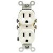
- 3 - 120v duplex outlet
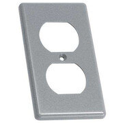
- 3 - duplex cover plate
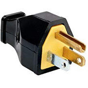
- 4 - female extension cord plug ends (make sure you get the ones shown below. If you get the traditional round one they are to big to plug in side by side. Home Depot and Lowe's both have the plug ends needed)
- 3 - 1/2" PVC 90's
- 3 - 1/2" PVC male adapters
- 3 - 1/2" conduit nuts
- 2 packs of 1/4" cable clamps (optional)
- 10' - 1/2 PVC conduit
- 21' - sacrificial extension cord
- 1 small box of sheet metal screws (if using cable clamps)
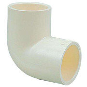

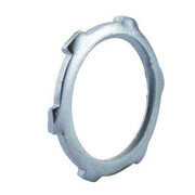
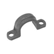
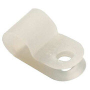
Now onto the interior layout of the electrical boxes.
1. Verify the chamber is unplugged.
2. Determine what wall you want the electrical boxes on and verify there is no wiring, drain lines or refrigeration piping in this wall.
3. Next draw three (3) vertical pencil lines from the floor of the chamber up about 8 inches. Then left to right space the lines 3 to 4 inches apart.
4. Next come up from the bottom of the chamber 6 inches and make a level line across all three vertical lines. This will be the center of the electrical boxes and where you will drill the holes for the conduit to exit the chamber.
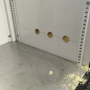
5. Where the three lines intersect drill a 1-1/8 inch hole through the wall of the chamber. This for the conduit to go through.
6. Punch out the 1/2 inch knockout out of the back of the backbox, put the male adapter in the backbox and thread the conduit nut (conduit nut goes inside the box and the smooth socket of the male adapter is on the back of the back box) on to secure the male adapter to the backbox. Repeat for all three boxes.
7. Next place the back box in the chamber with the male adapter centered over the 1-1/8 inch hole and push tightly against the chamber wall. Make sure the box is plumb/level then secure with sheet metal screws in the provided mounting holes. Repeat with all three back boxes.
NOTE: When using sheet metal screws to secure the back boxes it is a good idea to mark the mounting holes with pencil, remove the box and drill a 1/16 inch pilot holes. Then replace the box then fasten with the screws. Two screws per box is sufficient.
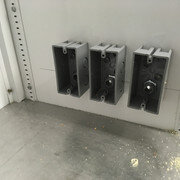
8. Now on the outside of the chamber push the 1/2 inch conduit through the side wall and into the socket of the male adapter in the back box. Make a pencil mark on the conduit flush with the exterior of the curing chamber wall then pull the conduit back out. Measure from the end of the conduit to the pencil mark. Cut 3 pieces to this length then insert all 3 pieces into the back boxes. This little section of conduit will act like a sleeve through the chamber wall.
9. Cut the extension cord into three sections (I like to go with extra so 7+ foot) piece to be trimmed to suit later.
10. Strip back the rubber outside sheathing on one end of the cord to expose the 3 wires contained within. Then strip back the insulation on the individual white, black and green wires.
11. Wire the duplex outlets White wire to silver screw, black wire to brass screw and green wire to green screw. Repeat for all three duplex outlets.
12. After the duplex outlets are wired pull the wiring through the backbox until the outlet is seated in the back box. Secure the outlet to the backbox with factory supplied screws on the outlet then install the cover plate. Repeat with all three outlets.
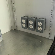
Now with power boxes installed time to move to the outside of the chamber.
13. Gather the 3 PVC 90's and cut 3 piece of 1/2 inch conduit approximately 8 inches
14. Now thread the tail of the wiring through the 90 and push the 90 over the wall sleeve in step 8. Repeat with all three wires.
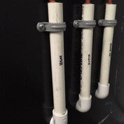
15. Now thread the wire through the 8 inch pieces of conduit and push into the top side of the 1/2 inch 90.
16. Verify the 1/2 inch risers are plumb then about an inch down from the top secure with the 1/2 inch conduit strap. Once secure seal the gap between the wall of the riser and the wiring with silicone. If you don't seal then gap in the summer hot humid air will settle in this gap then condense and water will run in the chamber through the electrical box.
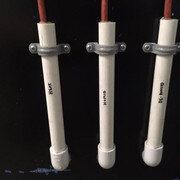
17. Wire on the male plugs to the three cords that are extension's from the interior electrical boxes. These plugs will get plugged into the controller 120v female outlets.
18. Next onto locating the Inkbird controllers on the exterior of the chamber. I like to put them with the digital display at or near eye level. Once you have them where you want them at the top of each controller is a tab with a hole in it that you use a screw to hang the controller on.
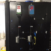
NOTE: If you are not absolutely sure of the controller placement you can use some double sided tape to temporarily mount the controllers. Then once you are satisfied with the location then use a screw to fasten them to the chamber wall.
19. Out of the bottom of the controllers are the 120v "function" outlets that will power the interior outlets. Pull these plug ends down to straighten out the wire and secure them the the outside of the chamber with double sided tape or there are also slots in the back that you can install small screws int he chamber wall then slip the plugs over to secure.
20. Next step is to drill 2 additional small diameter holes in the side of the chamber. One is for the humidity sensor the other is the temperature sensor. Seal around these holes as well ideally with something removable like a heavy duty tape or pliable putty to keep air out.
NOTE: You will have to measure the temperature sensor and humidity sensors to determine wheat size holes to drill. Mine were 1/2 inch for the humidity seanor and 1/4 inch for the temperature sensor.
21. Slide the sensors through the holes and into the interior of the chamber. Secure the humidity sensor about 1 inch down from the ceiling of the chamber with double sided tape. The Temperature sensor is also installed up high and not in the direct path of the condenser fan. Also make sure the temp sensor metal bulb is not touching anything just hanging freely.
22. Now its time to start plugging equipment in. The controllers each have a duplex plug with each plug perfuming a different task.
Temperature controller plugs are marked:
- Heat - This is where the heater plug in
- Cool - This is where the refrigerator plugs in
- Work 1 - This is where the dehumidifier plugs in
- Work 2 - This is where the humidifier plugs in

24. Now plug your "extension cords" coming from the interior of the chamber to the corresponding controller plug. Then plug the refrigerator into the "cool" plug the remaining three (3) plugs, plug into the outlets as outlined in step 22.
25. Fill the humidifier with water
26. Turn the refrigerator to the coolest setting.
27. Plug the Inkbird controllers to the 120v wall outlet and the controllers should light up. Now it's time to program the controllers and get the chamber up, running and controlling cooling, heating, humidifying and dehumidifying.
I run my chamber at 57 degrees and 80% relative humidity with a 2 point dead band.
NOTE: Dead band is an range plus or minus of set point. If you set the chamber at 57 degrees with no dead band when the temp rises to 58 degrees the cooling will run until it reaches the 57 degree AKA setpoint. But it will also overshoot and cool past 57 degrees to 56. Now that you are below setpoint the heat will come on to combat the over cooling. Then just like the cooling when the 57 degree set point is reached the heater shuts off but will overshoot to 58 degrees and the cooling kicks back on. Its a vicious cycle that will have the heat and cooling fighting to maintain a finite setpoint. To combat this if you add in few degrees of dead band now when the chamber is set at 57 degrees but the cooling will not kick on until the chamber reaches 60 degrees. So now at 60 degrees the cooling kicks on and at 57 degrees it shuts off and can over shoot to 54 degrees before the heat will kick on. Dead band simply allows newly introduced conditioning time to settle.Your home heating or cooling had dead band built into it from the factory.
This is how my Inkbird controllers are programmed:
Temperature controller
Temp set point (TS) = 57 degrees
Heating differential value (HD) = 2 degrees (dead band)
Cooling differential value (CD) = 2 degrees (dead band)
Alarm high (AH) = 62 degrees
Alarm low (AL) = 50 degrees
Compressor delay (PT) = 2 minutes
Temp calibration (CA) = 0 degrees
Display temp Fahrenheit or Celsius (CF) = F
Humidity Controller
Humidity set point (HS) 80%
Humidification differential value (HD) 2.0% (dead band)
Dehumidification value (DD) = 2.0 % (dead band)
Alarm high (AH) = 87.0 %
Alarm low (AL) = 50.0 %
Compressor delay = 0 minutes
Humidity calibration (CA) = 0 %
The alarm set points can be adjusted for tighter tolerance but then you get nuisance beeps every time you open the door. The alarms on either of controllers are audible only and will not operate or override the equipment.
Now that you have verified all the equipment is plug into the respective outlet all the equipment is turned in the "on" position, humidifier filled with water and the controllers programmed the chamber is now ready for the test phase.
Load some thermal mass in the chamber (6 packs, a case of water or a pot of water will work) close the door and watch the controllers enabling and disabling the different equipment to maintain setpoint. Do this for at least 24 hours or better yet for a couple of day to verify everything is operating as intended.
Once you are happy with the chamber operations now is the time to tidy up the wiring and/or permanently fasten the controllers. If the extension cords from the D/A chamber equipment outlets is too long simply remove the male plug end trim the wire to the desired length and refit the plug end. Then use the 1/4 inch nylon cable clamps to secure the wiring to the side of the D/A chamber.
NOTE: Anytime you are working on the electricals unplug everything from the wall outlets so there is no threat of electrical shock.
As one last side note: If you choose to you can easily revert the chamber back to a it previous life. Simply unplug and remove the heater, humidifier and dehumidifier from the interior of the chamber. Then reprogram the temperature controller to the desired temp. The nicety is if you are not curing year round you can reporose the appliance to be useful year round.
Congratulations! You have just built a Drying/Curing chamber that will hold extremely tight tolerance and give you the ability to produce/create some very high end product.
Enjoy,
Holly2015


