250 gal propane tank offset smoker build

  • Some of the links on this forum allow SMF, at no cost to you, to earn a small commission when you click through and make a purchase. Let me know if you have any questions about this.
SMF is reader-supported. When you buy through links on our site, we may earn an affiliate commission.

JC in GB

Master of the Pit
Original poster
OTBS Member
★ Lifetime Premier ★
Sep 28, 2018
3,574
2,774
Green Bay, WI
I am in the planning stages of a smoker build using 2 - 250 gallon propane tanks I am hoping to acquire next week.

After doing a few hours of reading, I have come up with a few questions that I hope are worthy.

Conventional flow offset VS reverse flow offset

Is there an advantage to putting in the extra time and materials to build a reverse flow unit? It seems the me that the physics of the cooker remain the same with a hot spot near the fire box getting cooler farther from the fire.

Stack combustion control VS firebox intake control only

I have seen most offset smoker designs use a free flow stack output design. This means that combustion is controlled entirely from the firebox air intake.
Is there an advantage in tuning the pipe for a specific flow?

Stack intake position

I know there is a great amount of debate over this issue so I am going to state my current understanding of this issue.
It would seem to me that the opening to the smoke stack should be no higher than 50% of the cook chamber height. This would help the area of the smoker farthest away from the fire box to maintain a bit more heat. Airflow over the food may be reduced very close to the stack but that may not be a big issue as air flow will still be significant.

Welding equipment preference

I have been trying to get information on what kind of welder would be best for a newbie to use on a project like this. The 2 answers I have gotten are either a MIG or a stick welder. Any opinions on this?

Current Plans

If anyone is interested, I have attached my initial round of calculations for the unit. Drawing is just a rough concept right now. Shout out to daveomak daveomak and gary s gary s for the wealth of information on building these units.


Thanks,

JC :emoji_cat:
 

Attachments

  • SMOKER 250_CALCULATIONS.pdf
    37.4 KB · Views: 715
Wow, that's going to be one heck of a project! With Dave and Gary in your corner I'd imagine you've already got it about 90% licked. I used to have a oxy-acetylene setup years ago and could run a decent puddle, never really got used to all the sparks when arc welding. Good luck and post up the build as you go, I'd love to watch this come alive. RAY
 
If you are into reinventing the wheel, go for it.... If not, over 25 years has been put into building a great RF smoker by hundreds of folks sharing their knowledge...
Many great folks on this forum contributed their knowledge and experience of RESULTS with their units and how they performed... With that wealth of knowledge I put together a "TEST" set of build ideas that folks built their smokers from... Then we evaluated the results and "updated" the build ideas.... repeat..... repeat..... repeat.... until we figured we had the best smoker a guy/gal could build in their garage...
The accolades from folks that actually our build ideas are overwhelming.....
If you think you can get better fire control, here is what two members said and posted pictures to confirm his smoker operating...


  • Like
Reactions: JC in GB
If you are into reinventing the wheel, go for it.... If not, over 25 years has been put into building a great RF smoker by hundreds of folks sharing their knowledge...
Many great folks on this forum contributed their knowledge and experience of RESULTS with their units and how they performed... With that wealth of knowledge I put together a "TEST" set of build ideas that folks built their smokers from... Then we evaluated the results and "updated" the build ideas.... repeat..... repeat..... repeat.... until we figured we had the best smoker a guy/gal could build in their garage...
The accolades from folks that actually our build ideas are overwhelming.....
If you think you can get better fire control, here is what two members said and posted pictures to confirm his smoker operating...


daveomak daveomak not trying to re-invent the wheel at all. I am looking for just what you are providing here. Even if the plans are cut and dried, I like to understand the science and math behind it. Kind of helps you know what to do if your puzzle is missing a piece and helps you troubleshoot if things don't run as expected.

I used the Feldon's online calculator for my initial numbers.

I am simply a seeker of knowledge and want to expand my skills. The knowledge I have gained here about BBQ cooking could fill a fairly large book by now and I am just getting started. :emoji_smile_cat::emoji_smile_cat:

Make no mistake, your valuable help and information are always appreciated.

All that said, do you have plans for the 250 gallon smoker all drawn up? I would appreciate if you could direct me to them....

JC :emoji_cat:
 
Last edited:
  • Like
Reactions: JC in GB
Here are the plans.....


Awesome. Thanks.

JC :emoji_cat:
 
daveomak daveomak I am a bit confused by the baffle plate calculation.

Are there more than one plate installed in the smoker or is this one plate what you need to provide the proper air flow?

I am looking at other builds and I see one or more plates with gaps in between. Is this how the reverse flow smoker is supposed to be laid out?

I think I can handle the rest of the calculations from your tutorial.

Thanks,

JC :emoji_cat:
 
Under the RF plate... That sq. in. area, looking at the opening from the end of the CC....
All those areas from the FB to the stack are to reduce friction loss from air flow....
Increasing the stack diameter will do no harm... It will just insure there is no friction loss from air exiting the smoker..
Friction loss, in a convection type smoker, is a killer because pressure differential and gas density are the only things driving the draft... They aren't too powerful...

Basic RF Design drain valve.jpg
 
  • Like
Reactions: JC in GB
daveomak daveomak I am a bit confused by the baffle plate calculation.

Are there more than one plate installed in the smoker or is this one plate what you need to provide the proper air flow?

I am looking at other builds and I see one or more plates with gaps in between. Is this how the reverse flow smoker is supposed to be laid out?

I think I can handle the rest of the calculations from your tutorial.

Thanks,

JC :emoji_cat:


Those plates are for an Offset smoker.... A Reverse Flow uses a solid plate... The plate spacing, on an Offset, is to adjust the heat to the food grate... The gaps allow heat to rise to the food..
 
  • Like
Reactions: JC in GB
 
Those plates are for an Offset smoker.... A Reverse Flow uses a solid plate... The plate spacing, on an Offset, is to adjust the heat to the food grate... The gaps allow heat to rise to the food..

Thanks for that information.

I will redraw my plan using the calculations you provided.

JC :emoji_cat:
 
I have redone my concept and calculations. The design is now in line with the example daveomak daveomak provided.

Updates drawings attached. Drawings are not to scale.

JC :emoji_cat:
 

Attachments

  • SMOKER 250_CALCULATIONS.pdf
    57.9 KB · Views: 243
  • SMOKER 250_CONCEPT.pdf
    30.2 KB · Views: 176
Use 1/16 or 16 gauge for the door gap seal material... Skip weld or blind weld to the door so the door doesn't warp from the weld..
Hinges... bullet hinges may cause the door to not seal unless you know what you are doing... design a hinge that allows for tweaking by bolting to allow for spacers to be inserted... The hinge pin needs to be 'outside' the door seal flange to facilitate opening without interference....
Cut the opening for the FB past the weld seam to make fit up of the RF plate much easier.. The FB needs to be wider than the CC at the weld seam... Weld the RF plate to the top of the FB... The RF plate can be skip welded... When installing the RF plate, and you have it ready to go, with a hydraulic jack, compress it in the center to form a valley for drainage then tack weld it in place... You only need a 1/2" valley or so... When you compress the RF plate, it will naturally drain away from the FB.... Leave a 1" or so lip at the FB/CC opening when cutting it out to serve as a dam to stop grease from flowing into the FB.... You should have a drain on the RF plate and the CC for cleaning... A clean out hole in the bottom of the FB is nice.. A 4" hole ,with a steel plate sitting on it during use, works well... It should sit flat so it's close to air tight.. wood ash will seal it during use... or dirt... I like a layer of dirt or sand to protect the bottom of the FB... dirt works very well..
All of the above is "so it says in fine print somewhere".....
 
  • Like
Reactions: JC in GB
Use 1/16 or 16 gauge for the door gap seal material... Skip weld or blind weld to the door so the door doesn't warp from the weld..
Hinges... bullet hinges may cause the door to not seal unless you know what you are doing... design a hinge that allows for tweaking by bolting to allow for spacers to be inserted... The hinge pin needs to be 'outside' the door seal flange to facilitate opening without interference....
Cut the opening for the FB past the weld seam to make fit up of the RF plate much easier.. The FB needs to be wider than the CC at the weld seam... Weld the RF plate to the top of the FB... The RF plate can be skip welded... When installing the RF plate, and you have it ready to go, with a hydraulic jack, compress it in the center to form a valley for drainage then tack weld it in place... You only need a 1/2" valley or so... When you compress the RF plate, it will naturally drain away from the FB.... Leave a 1" or so lip at the FB/CC opening when cutting it out to serve as a dam to stop grease from flowing into the FB.... You should have a drain on the RF plate and the CC for cleaning... A clean out hole in the bottom of the FB is nice.. A 4" hole ,with a steel plate sitting on it during use, works well... It should sit flat so it's close to air tight.. wood ash will seal it during use... or dirt... I like a layer of dirt or sand to protect the bottom of the FB... dirt works very well..
All of the above is "so it says in fine print somewhere".....

Awesome. Thanks for the tips. A lot of good advice right there.

If all goes well, I will have twp propane tanks to work with next week.

JC :emoji_cat:
 
Set the RF plate at it's calculated height from the bottom of the CC... Set the lower food grate 3-6" above the RF plate... If it is at 3", and you find for certain things they get too hot, a steel plate can be set on top of the RF plate with some spacers holding it up to make an air gap insulator.. or a sheet pan... or aluminum foil... It doesn't take much to deflect 25F of heat... for special things... You can even make a small rack to sit on top of the lower cooking rack....
Don't sacrifice cooking space by having a high lower rack... There are easy ways to get around a hot spot... Some folks really fret over hot spots.. brown up your chicken skin, on a hot spot, iffin you got one.... they can come in handy....

The easiest way to get around a hot spot is..... Learn to use the upper air inlet to move heat from the FB to the CC... Then learn how to adjust the lower air inlet to control the fire temperature... Start with the upper inlet wide open... tweak the lower air inlet to adjust the heat... You should be able to run the smoker at the same temp as the FB which conserves fuel and makes the smoker darn close to the same temp everywhere..... The upper air inlets serve the same function as a fan in your forced air heating system.....
 
  • Like
Reactions: JC in GB
daveomak daveomak I am still in the calculating stages of the build and I have run into an problem with the FB to CC opening.

Here are the numbers I got from the circle calculator.

I plugged in the numbers from my drawing and it seems that if I won't have enough area from the FB to the CC if I place the RF plate where the calculator suggests. The FB/CC opening is as wide as the RF plate. This would only work if I cut the entire half circle under the RF plate out. Is that what I am going to be doing? What did I do wrong?

I guess what I am asking is the entire area under the RF plate open for the CC/FB opening?


1593528924104.png


1593529008028.png


JC :emoji_cat:
 
Last edited:
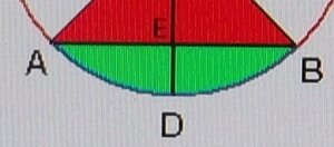
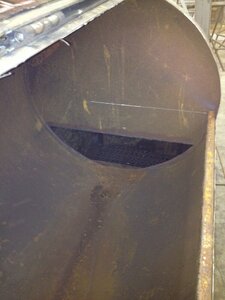
The green area is what you did the calculations for... Yes.... cut out the green area... When you figure out the area needed for the FB/CC area, add in the thickness of the CC and the thickness of the top plate on the FB... Cut out the end of the propane tank... cut PAST the welds for an easier fit up... slide the FB into the opening and weld the RF plate to the top of the FB... Cut out the opening to the FB.... Leave a small amount of metal for a dam to stop grease from flowing into the FB...


5f7 2.jpg

Grease dam for the FB....
FB dam.jpg


FB/CC opening
FB CC Opening.jpg


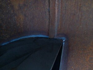
Weld seam on a propane tank....
Propane Tank weld joint INSIDE.jpg

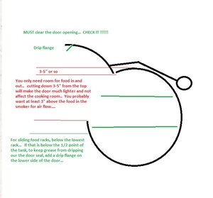
Adequate door opening for a smoker...
CC door  opening height.jpg


...
 
  • Like
Reactions: JC in GB
SmokingMeatForums.com is reader supported and as an Amazon Associate, we may earn commissions from qualifying purchases.

Latest posts

Hot Threads

Clicky