I read through this post on how to Rewire and MES for the Auber PID controller: https://www.smokingmeatforums.com/media/openedpannel-png.547735/
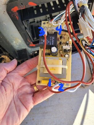
But it’s pictures do not match what I am finding with me MES… see attached images of what I’ve found. The one with the black post is the power cable coming into the unit. The one with the black box with holes is adjacent and receives power. The black box has special Y-shaped screws that a Phillips head will not fit into. Any ideas? Was expecting an easy rewire job and found all this nonsense.

Root cause of why I went with a PID option was that my unit’s user interface does not power up and the buttons are non-responsive. So I cannot use the smoker.
But it’s pictures do not match what I am finding with me MES… see attached images of what I’ve found. The one with the black post is the power cable coming into the unit. The one with the black box with holes is adjacent and receives power. The black box has special Y-shaped screws that a Phillips head will not fit into. Any ideas? Was expecting an easy rewire job and found all this nonsense.
Root cause of why I went with a PID option was that my unit’s user interface does not power up and the buttons are non-responsive. So I cannot use the smoker.