JP's GOSM build mods

  • Some of the links on this forum allow SMF, at no cost to you, to earn a small commission when you click through and make a purchase. Let me know if you have any questions about this.
SMF is reader-supported. When you buy through links on our site, we may earn an affiliate commission.

jbpace

Fire Starter
Original poster
Mar 4, 2008
34
10
Germantown, TN
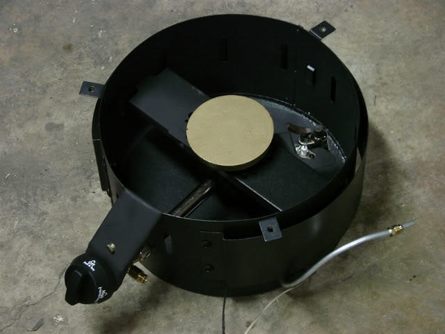
As I often read before ordering, GOSM smokers are not packed well for shipment. Heavy cast-iron boxed parts bouncing around loosly inside the smoker body bent the racks up/down and generally out of place. I tried straightening them with pliers, but that was too much of a good thing - some of the welds broke. I ended up taking the racks out and used a MIG welder to strengthen every joint:


Took the above photo before painting, but I subsequently covered the racks with Dupli-Color Engine Enamel with Ceramic (silver) I found at Auto Zone (rated to 500 deg F) to prevent rust.


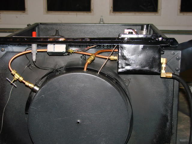
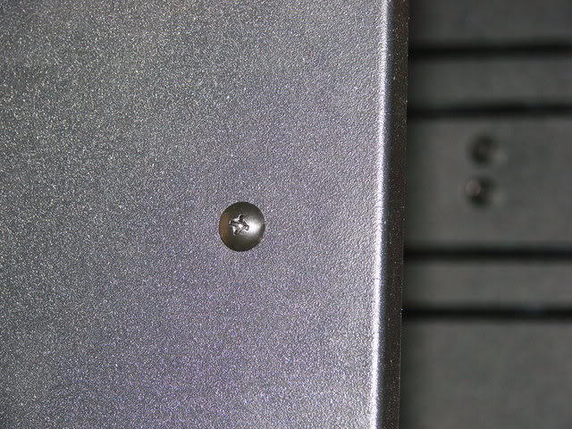
I then put the racks back in and added center supports to strengthen both the shelves and the sheet metal sides (NM/SE cable, One Hole Midget Straps, 1/4"):


These were secured with some nice bolts I found at Lowes (10-24 x 1/2", Fan Blade Screws, Ceiling, Bronze):


I then added the temp probe port as suggested by travcoman45 by cutting a hole through the smoker body (yes, it hurt to drill a new smoker ;-):


and inserted the 1/2" UF Water Tight Connector fitting:


From there I moved on to adding a thermostat controlled gas valve, but that's for a later post.

Good smoking,
Jon
 
Last edited:
Since I was on a roll I decided to add a thermostat controlled gas valve to make the GOSM as accurate and easy to use as possible (sorry, not a purist). I started by securing parts - first, a 750mV pilot burner/thermocouple generator ($40 for Grainger #1RC59):


a 60-250 degree F thermostat ($71 at http://www.instawares.com/thermostat...0-1010.0.7.htm):


and a millivolt gas valve (White Rodgers model 36C03U for $20 on eBay or $95 for Grainger #2E854):


I converted the gas valve for LP using a conversion kit (Grainger #2E731) to hold the regulator open:


I mounted the capillary bulb for the thermostat right at meat height, about an inch away from the side wall. The capillary tube was hidden behind an aluminum channel (three sided rectangular cross section) that was painted black (using Dupli-Color Engine Enamel with Ceramic to touch up all raw areas, with a final coat when done):


and wired the pilot light/generator next to the relocated spark igniter on a custom bracket next to the burner:


close-up on the new assembly (notice the spark igniter is next to the generator - didn't work when I mounted it near the pilot burner):


Next step is a test drive. Wish me luck!

Jon
 
Last edited:
The test drive of the smoker thermostat mod did not go well - it started well, but the second time the burner lit to reheat it never shut off.

Disassembled the controls and discovered the wire I used to hook up the thermostat had melted and shorted, causing the gas valve to lock open. Not a good sign...


For those familiar with a GOSM, the gas valve was mounted through the top right side of the front panel, surrounded/supported by 22 gauge sheet steel. This placed the control wiring at the top, next to the bottom of the smoker box.

Now I humbly ask your suggestions on how to change my setup to prevent another dangerous performance. As best I can guess, I need to do at least one of three things:

1) Use high-temp (e.g. thermocouple extension) wiring to hookup the thermostat, and/or

2) insulate the gas valve/wiring (but I have no idea what I could use), and/or

3) relocate the gas valve further away from the smoker box proper.

If I did relocate it, where could I put it? The tubing required for the smoker (1/4") isn't strong enough to support the weight of the valve, so I have to fabricate something to support it, but the steel involved becomes an instant heat conduit. Maybe I'll think of something when I'm not quite so bummed, but I would really appreciate any suggestions my more knowledgeable peers could offer.

Thanks,
Jon
 
Last edited:
Jon can you post a picture of where you had the gas valve and thermo state mounted?? I would thing if you made a nice bracket to the side of the unit leaving about an inch of air space you should have no problem with melting wires. the gas valve and thermosta control needs to be outside and away fromt he burner unit. high temp wire may work but good luck tring to find a short length of it.
 
I'll take photos of it when I get home tonight and post them. The thermostat is mounted in the hole where the gas burner control used to reside. The burner control (which no longer needs to be operated) can be seen hard mounted to the burner housing in one of the photos above.


Because of the amount of transportation this smoker will endure, I'm trying my best NOT to mount anything outside the existing profile. I could go lower - possibly flipping the gas valve to put the wiring on the bottom - but I need to avoid moving outside.


I've found some sold by the foot on eBay. Think this would work:

http://cgi.ebay.com/ws/eBayISAPI.dll...m=180168509699

Thanks,
Jon
 
Jon that wire you found is not high temp it's just thermo couple wire. you need something like this :

http://cgi.ebay.com/Teflon-16awg-Sil...QQcmdZViewItem

or do an ebay search for high temp wire. just keep in mind 200c = 392F

Don't need the pic unless you want to post it I can see things now. Also it looks like the wire jsut got hot in one spot you might want to re route it also getting it away from that hot spot. Mod looks great might have to try it myself. once you get all the buggs worked out of course
 
I was thinking what with all the smokers within the SMF, we could come up with some great smokers of all types, that would sell like dry wood.
 
Creative idea
PDT_Armataz_01_37.gif


Thing that might concern me, if the potential exists to trap gas inside if your pilot sensor fails or the wire shorts (or opens).
 
Excellent concern, and one that is addressed in the design. This style pilot light/generator generates a 750mV signal when the thermopile is heated by the pilot light. If the pilot isn't lit, or if the wire is cut, the signal goes to zero.

This is coupled with a millivolt gas valve that is powered via the incoming 750mV signal. That signal is required to open the pilot light and main burner valves. Without the signal, everything closes.

I assembled the burner and tested the safety system before installing it. With the burner on High I extinguished the pilot light with compressed air. In ~15 seconds all gas flow stopped. That's within the design specs and is basically the time required for the thermopile to lose enough heat to stop generating voltage.

Once I overcome the wiring issues it ought to be a nice setup.

Jon
 
I've placed the gas valve assembly back where it was, but didn't replace the burner assembly or gas lines/wiring.

The front of the original panel was modified to this configuration:


Close-up on the thermostat control:


and a close-up on the gas valve (the wiring connectors are under the raised metal cover, they come in from top of the picture - the side nearest the smoker floor):


To give you and idea of how much clearance the metal cover on the gas valve had (~1 inch from the burner cover), here's a shot from straight under the assembly:


and finally a shot showing the clearance (~1 inch) below the bottom of the smoker floor. You can see remnants of the wiring hanging down the left of the gas valve body:


I checked Lowes after work and found a couple options:
  1. 1/4" gypsum board, but I'm afraid the weather would destroy it
  2. 1/4" HardieBacker, appears to be some form of cement board
I'm thinking of covering the original metal cover I made with one of those options then covering that with another metal cover to hold it all together.

Sound feasible?
Jon
 
Last edited:
Jon

I think there are a lot of folks here interested in what you are doing. Please keep us posted on your progress and if possible post sources and part number of the components you use.

Thanks
LB
 
you can also try to use some thin, 16 gauge steel to make a heat shield to protect the wire also, would last as long as the smoker, that with some high temp wire you should be all good to go. Looks like you only had on hot spot on the wire also. Might want to try to re route it away from that hot spot.
 
jbpace, I really am interested in your conversion. Keep up the posts as you work through this project.

You say where you got the Gas Valve and the Pilot light but not the thermostat and the Thermocouple. Please provide your source.

Will a gas water heater thermocouple work here?

Does this arrangement provide proportional control or does the gas cycle off and on? I am simply ignorant about how the thermostat controls the valve.

I have ofter wondered if a gas water heater arrangement couldn't be used to control the GOSM. The temperature range might not be compatible.

Keep up the good work.

Reagrsd,
Aubrey Page
-------------

OTBS #007
 
Sorry. I've gone back and added part details above.


I convinced myself it wouldn't work because water heaters aren't designed to go over about 180 deg F. If it weren't for the integral thermostat there's no reason it otherwise wouldn't.

Plus, water heater thermostat dials generally aren't labeled in degrees. At least the ones I've seen are labeled A, B, C, etc.


Unfortunately, it provides on/off control.

The thermostat is an open/close switch. These gas valves open when the thermostat ciurcuit is closed. This particular thermostat is always open (gas off) when turned "off". It closes the circuit (gas on) when turned "on" if the sensed temperature is below the set temperature. Once the sensed temperature is above the set temperature the circuit opens (gas off).

When I first tested it, the one time it shut off (before subsequently melting the wire) my smoker overshot set temp by 40 degrees. That was on initial rise, and I had the burner control on high, so I'm not sure how representative that will be of the final design.

My plan is to remove the stock burner control and add a needle valve to keep the burner low enough that it doesn't overshoot.

eek.gif
I'm humbled such a senior member of the OTBS would be interested in my project. I just finished cutting HardieBacker to use for insulation. Hopefully I'll have everything welded & painted this weekend.

I'll keep updating as I plod along,
Jon
 
I know it's probably overkill, but it now works!!! After the above meltdown, here are the steps I followed. First, I bought 1/4" HardieBacker cement board and cut pieces to cover the bottom & sides. I then surrounded that with 16 gauge steel - using the steel to hold together the cement insulating boards. Not shown in this photo are the rails I later welded to the sides of the box to give me something to rivet to the front panel (visible in the last picture):


You can tell the input (far) side of the gas valve appears to have the original hose assembly - and indeed it does. I disconnected the hose assembly from the adjuster valve:


and discarded the valve. I bought brass fittings to join the hose to the new gas valve, which can be viewed further down.


I then needed a nozzle to vent LP into the burner tube. I bought parts at Lowes (labels in the pic) and assembled them with LP sealing tape:


The hole you see in the square head plug above was drilled with a #56 bit (0.046") that closely matched the old adjuster valve nozzle.


I then took a rasp and filed down the coupling until it fit in the burner tube opening (sorry it's fuzzy):


and connected everything with 1/4" copper tubing rated for LP gas, inserting a needle valve in the main burner plumbing for final burner control:


You'll remember my melted thermostat wire - what I did was figure out where I could cut the wire that came off the thermopile (it comes with the pilot generator assembly) to use lengths for both signals. It appears to be copper wire double insulated with glass mesh. It strips with standard wire strippers.

You can also see I rotated the burner 60 degrees counterclockwise by drilling new holes and welding over the old ones. That is required to easily fit all the new hardware.


From the front you can see I used the old spark igniter hole for the new thermostat dial and drilled new holes for the (relocated) spark igniter and cover plate. The old adjuster valve hole is in the center of the front panel, covered by the cover plate:


A close-up of the gas valve showing the routing of the wiring (around the body clockwise from the top, then going out of the metal housing at the lower left behind the control panel):


I still need to create an electrical/gas wiring drawing. That will show up as soon as I find something to create it in jpeg format.

Hope that helps anyone who wants to try similar mods,
Jon

addendum:

finally got a photo of the cover I fabricated for the gas valve, complete with grease from my first smoke:

 
Last edited:
After adjusting my needle valve so that the burner was on 90+% of the time, I let everything cool overnight and started it up while recording the temperature each minute. The top vent was fully open and the lower vents were both closed to the stops. Temps were measured with a Maverick Redi-Chek ET-73 placed just above the second shelf from the top. Ambient temperature was 78 degrees. Smoker was set to achieve 225 (but the thermostat dial needs to be on 213 - go figure):


After reaching a steady-state temp, I wanted to see what happened when the system was disturbed. I opened the front door as far as it would go for 60 seconds, then closed the system and recorded temperatures each minute (note the scale is greatly magnified from the previous chart, so the swings only appear larger):


While there was nothing in the smoker except water in the pan, I thought the results looked pretty good. The smoker loses heat amazingly quickly when the burner turns off, but once the needle valve is set it seems pretty steady.

Please let me know if you feel it's not stable enough for a good smoke - I've never had this precise temp measurement before.

Jon
 
Last edited:
SmokingMeatForums.com is reader supported and as an Amazon Associate, we may earn commissions from qualifying purchases.

Hot Threads

Clicky