RF Build: A Story in Pictures

  • Some of the links on this forum allow SMF, at no cost to you, to earn a small commission when you click through and make a purchase. Let me know if you have any questions about this.
SMF is reader-supported. When you buy through links on our site, we may earn an affiliate commission.
 
I was curious why you would build a frame for the firebox when it was 3/8 plate. Doing a double it makes more sense now.
If I had it to do over again, I'd just use angle iron to form the corners (edges).

Going to single-wall has its advantages: now, I can put a hinged lid on top of the firebox and use it as an oven for beans, etc.
 
He lives!

Finally got a little more work done on the smoker, mostly by a stroke of good fortune.  For those in the Norman/Oklahoma City area, the University of Oklahoma has built a facility called the "Innovation Hub;" a very slick idea, it has conference rooms, collaborative spaces, classrooms, and--most useful for building things--the FabLab.  The FabLab has tools including 3D printers, laser cutters, metal- and wood-cutting band saws, a drill press, table saw, welding equipment, and machinery that was recently donated and hasn't yet been set up (they're waiting on 3-phase power to set up the Bridgeport mill).  And, best of all, it's open to the public for free!

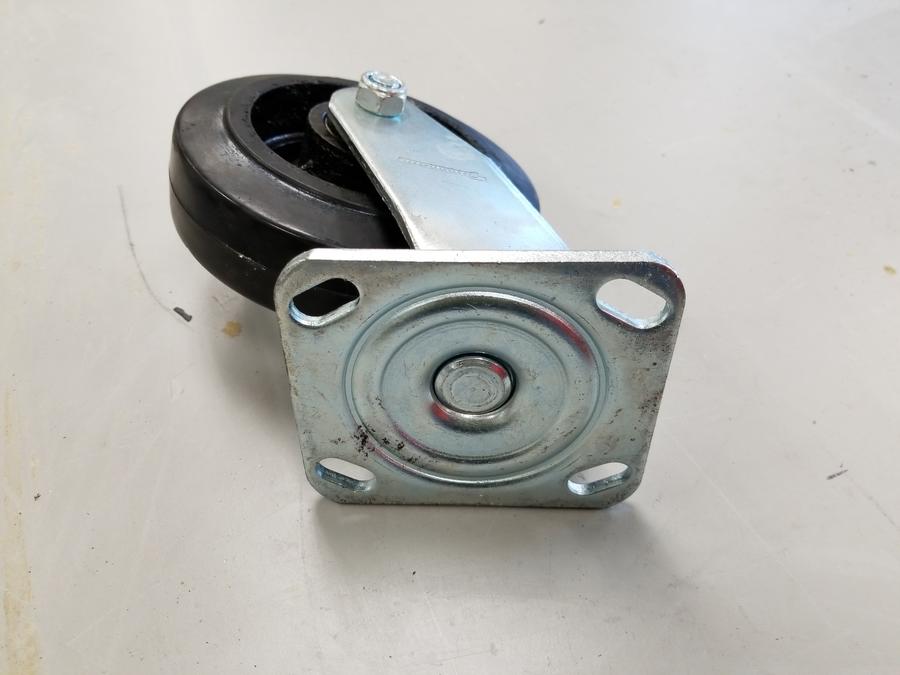
So, when last I posted, I was looking into building the undercarriage so I could get things moving (ha!).  I'd bought the casters noted in post no. 37 above, and done the calculations to build the frame.  Next up is to A) cut the steel tubing for the frame, B) weld it up, and C) get the wheels mounted.  For various reasons centering on which equipment was available at the time, I decided to work on mounting the wheels first.  The casters in question look like this:


I thought of bolting directly to the frame, but I didn't want to drill through the tubing, blind nuts are a pain, and that would leave the fourth corner unsupported; welding them avoids the first two issues, but not the third, and adds the issue of cleaning off the zinc before welding, and the possibility of messing up the bearings with heat or paint.  I decided to make some mounting plates so the wheels would be removable.  The question, then, became how to get the holes in the mounting plates to align with the top plates of the casters.

Welcome to the FabLab.  First, scan the top plate on an optical scanner.


Next take that optical scan to a workstation, import into Adobe Illustrator, and trace the edges; use the traced edges to place circles of appropriate diameter in the center of the elongated holes.  Eliminate all unnecessary marks and end up with a cutting diagram for the laser to make a drilling template:


(Modified to be easier to see, and dimensions are lost in the conversion to JPG.  If anybody would like a copy of the Adobe Illustrator (.ai) file, drop me a note and I'll be happy to share).

Send that to the laser cutter for use on a convenient piece of scrap.  The result:


Test-fitting:


Excellent!

Now, what to use for the plates themselves?  It turned out I had a piece of 1/4" diamond plate in the garage doing nothing, so I decided to press it into service (we'll see more of it later):


The red marks are rough outlines I drew with a Sharpie just to get a general idea of where I'd be cutting so I didn't need to take the whole 8' long plate to the FabLab.  A little time on the horizontal band saw (with a brand-new blade; lucky me!):


gave me these:


Now, to drill.  My first thought was to clamp the template to the steel and go to town, but this left a couple of issues: 1) how to center the pilot hole, and 2) if anything is off-center, the drill bit will happily cut a new hole in my template, defeating the purpose.  Fortunately, the FabLab has not only the equipment, but knowledgeable, helpful staff, one of whom (Colton) helped me substantially throughout the process.  He showed me how to put some paint on the back (someone had used up the Dykem as paint, so we used spray paint as layout fluid), then use a drill bit (matching the template holes, making it self-centering) to transfer the hole centers to the steel:


You can just barely see where the tip of the drill bit put dots in the paint:


From there, we used a center punch to dimple the steel on the marks, then moved to the drill press.  Drilling the pilot holes:


The slotted blocks to hold the plates were Colton's idea, and a very good one.  Made from 2x4 scrap on the table saw.  Next, I bored out the holes to 29/64", just a hair over the 7/16" bolts I plan to use (the extra is to give some room to weld the bolts in; more on this later).
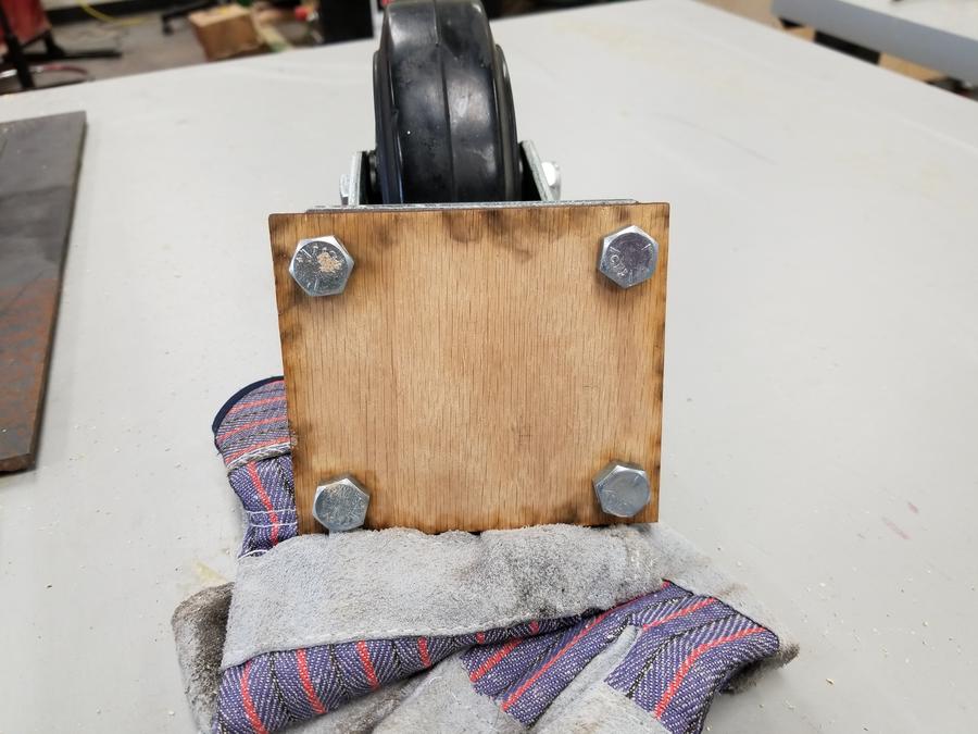

All completed:


Test-fit: like a glove!


Next update will be next Monday (the FabLab has limited hours during the summer), when I get checked out on the welding equipment.  I'm also going to try to cut the steel tubing for the legs; if I can get those cuts done, I can start working at home again at my convenience instead of theirs.
 
Congratulations on passing the bar exam. My niece has started studying for her to take it in a couple years....
If my math is correct--and there's a reason I'm a lawyer, not an engineer*--then your niece should probably be taking the MBE (multistate) portion today.  Best of luck to her!

* That reason would be Calculus II; I started school as an electrical engineering major, but Calc II kicked my butt.  I finally got through it with a grade that would let me continue in EE, but decided that--discretion being the better part of valor--my talents were better spent elsewhere.
 
So, almost a year later, a small update:

I did end up getting the legs cut, but somehow never posted an update, and can't find the pictures, so I'll fill in more about that tomorrow.

I've been very busy with various other things, and the extension cord I use to run my grinders went walkabout, so I kind of laid off for a bit. I couldn't sleep tonight, though, and having replaced my extension cord last week, decided to get a little work done.

For reasons that will become clear later (the plates will be welded directly to the running gear), I need the plates to be reasonably flat on top, so bolts are out; studs are the order of the day. I could cut the heads off of sixteen bolts, but that seems like a wasteful way to get there; all-thread seems perfect. The question then becomes how to get the all-thread cut. Using a saw would result in the inch-ish long studs being launched across the room as soon as the cut was done. So, I got clever: I stacked the plates to establish height, topped with the wooden drilling template to act as a sacrificial face:
20180521_012419.jpg

Thus clamped, the cut-off stud would remain in the hole (the bolt was to maintain alignment; I was able to cut several before having to unclamp by keeping things well-aligned, then removing the bolt when I needed the hole).

Next: clean up the holes with a wire brush so that they weld well:
20180521_020910.jpg


I'll clean the entire plate in the blast cabinet later; this was just for welding the studs.

Now, the question becomes how to weld the studs. I want to weld from the top, rather than from the usable thread section (I discovered this when working with my test piece; I was undercutting into the thread, and also depositing enough weld material to keep the wheel from seating properly. Protip: always have some test pieces before you work on the real steel!), and I wanted them to sit just below flush with the plate so it would act as a sort of shallow plug weld. Enter solution, part I: a stud, inserted from the back, with a nut to limit the depth:
20180521_020913.jpg

20180521_021008.jpg


Note that the "head" of the stud is just below the level of the plate; adjust the position of the nut to get the depth you want.

Now, on to the next issue: how to ensure that the studs are all square in their holes--if they go all catty-wampus, they won't fit the pattern of the caster. Enter solution, part II: one last use for the wooden template.
20180521_022823.jpg


20180521_022844.jpg


I thought I was fairly clever here:knowing that three points determine a plane, I only put the limiting nut on three studs, leaving the fourth to float freely against both the table and the plate. Clamp it securely, in this case not with a C-clamp but a conveniently strong spring clamp:
20180521_022926.jpg


The particularly observant will recognize that as the ground clamp for my welder. Bingo: strong mechanical clamping and great electrical ground. Can't beat that!

The results:
20180521_023623.jpg

20180521_030040.jpg


All four plates, when resting on their "legs," have less than 1mm of wobble, so I definitely think the concept was sound for getting them even. And, upon test-fitting:
20180521_023604.jpg


The casters fit the plates beautifully. I couldn't have asked for a better outcome than this, and I hope my methods will be useful to somebody else sometime down the road. I'm tickled pink with the results.

Updates on the legs later when I'm more awake.
 
Last edited:
Alright, so the legs. This was about a year ago, a week or two after I drilled the plates, but somehow, the post disappeared.

I'm building this with a 24" barrel, but I wanted a wider base for stability; I settled on 36" wide. Obviously, that means some splay. To make the leg-barrel interface easy, I decided to stub them straight in to the barrel, then have a bend later to have the legs vertical. 45° seemed the easiest way to do that. I spent a good half-hour screwing around with my CAD program (Sketchup; I'm cheap frugal) and getting nowhere before I got frustrated. I grabbed my old TI-82, scrounged up new batteries for it, sat down with a sheet of paper, and five minutes (and a quick thanks to my old trig teacher) later, had the lengths worked out for the two segments of each leg (square cuts on one end, 22.5° on the other, mated on the bevel to make a 45° bend), as well as the stringers and crossmembers. Excellent; back to the Fab Lab.

I got there only to discover that--like an idiot--I'd left my design specs at home. Dammit! Okay, I can deal with that; I sat down with another sheet of paper and re-figured everything. For some reason, the vertical segment height seemed wrong, so I double-checked my sines and cosines and came up with the same number. Alright, let's go cut. I cut them, tacked the angles on their welder (it was convenient), and took stuff home. Somewhere along the way, I welded the previously-tacked angles. A quick test layout on the floor showed that I had significantly goobered.

Protip: when your math teacher told you to check your work, she didn't mean to just plug the same numbers into the calculator; she also meant sanity checking: is this answer reasonable in light of everything I know. That little voice in the back of my head about the vertical was the sanity alarm going off, and I just silenced it rather than asking what it was trying to tell me.

So: leg extensions. Got them cut, took them home, and proceeded to ignore everything until today. Today, I assembled the legs. First, the legs as built, with the short side beveled and wire-brushed:
20180521_173234.jpg


Yes, the angle welds look like crap. They're strong, and a bright flashlight shows that I got good penetration, but they'll get some grinder time to clean them up--I hate looking at my mistakes. Similarly, the welds at the extension will probably be ground and flap-disked to disappear completely: they're much better welds, but their very existence offends me.

Extensions, beveled and brushed:
20180521_173344.jpg


Arranged to check sanity:
20180521_173358.jpg


Looks good. I grabbed a couple pieces of scrap to preserve alignment; combined with the table, everything came out nice and straight. Clamp them down and tack (you can't see it, but there's also a tack on the vertical face nearest me):
20180521_174241.jpg


All welds, save for a handful of tacks, were done in the flat position. With my welding skills, I already get enough grinder practice; no sense adding difficulty by getting out of position. The end result:
20180521_181042.jpg

20180521_181032.jpg


I'm much happier with these welds! Again, full-penetration, but much smoother, and I even had good tie-ins between beads.

Next step: assembling the legs, stringers, and crossmembers into complete running gear. That may be a little while in coming, as I'm just about out of gas (anybody want to send me a donation, care of my local Airgas)?
 
A bit more progress: I got one of the leg assemblies done. I need to build a second identical assembly, then tie them together with spars (which will run parallel to the long axis of the smoker; in this picture, they'd be coming straight up at the viewer); the "doghouse" shapes sit on the ends of the cook chamber and will meet the barrel (24" diameter, 55" long) at right angles (think about how a Corsair's wing fits against the fuselage).
20180608_023151.jpg


A test-fit suggests that the height (with the extensions) will be just about right when mounted on the (large-ish) casters.
 
SmokingMeatForums.com is reader supported and as an Amazon Associate, we may earn commissions from qualifying purchases.
Clicky